Good evening from Minnesota, I’m in the process of wiring my 12 row planter with electric shut offs on the row units. I’m also wiring an electric starter fertilizer pump to a WEMC 250 controller for the time being. I want to integrate the implement switch from this unit to AOG. I’m wondering how I wire just a normally open to closed circuit to aog without the need for voltage or ground. My first thought is using one of my 16 relays on the SK21 rate controller, how do I change code so the pump stays on while mapping with row units on until the last section shuts off using maybe one of the relays with my 2 switch wires going through the relay. Second thought is using the implement switch on the version 5 pcb? But that doesn’t know when one of my 12 relays is on in the rate controller right? Thank you very much!
So you would like one relay to come on when any of the 12 row relays are on and only turn off after all the 12 row relays are off?
There could be 3 types of relay definitions. 1- section relay turns sections on/off. 2- Slave relay, turns on when at least one section relay is on and only turns off after all section relays are off. 3 - Master relay, turns on when sections relays should be on (start of a pass, etc.) and turns off when all section relays should be off (end of a pass, etc.). As requested on github issues this relay would turn off and the section relays could remain on. It could control a master valve for instance.
Yes, turn on when at least 1 relay on and off after all 12 are switched off. Do I have to change code for that?
Yes the code has to be modified.
Check if either section byte is greater than 0, set pin _____ High. That should do it.
That would work. Put an if statement in the ino to turn on the right relay.
Isn’t this function simple enough to be performed by HW, 8 diodes would do it. No need to repeat the SW changes every time a SW update is releases?
I have no idea how this pump system works, is there a pressure reservoir or would the pump need to be started some time before any section activates?
The pwm pump is turned on as soon as the planter starts seeding. The pump is dribbling fertilizer into the seed furrow through lines with anti drip orfices right at the furrow. So soon as pump is on its dribbling the already charged line. I’m running this on a mid 1990s white planter and an old International 1086. Only options are tying into the rate controller for this as only when seed is being put down is when the fertilizer is on. Sorry, but what is the SW update? What is the HW 8 diodes that your speaking of? I was thinking that kentstuff and sk21 maybe had it for me on coding to get one of the relays I don’t use anyway to be programmed to do this function. I’ve never written or changed code, but thinking I can figure it out this morning! ![]()
He means that you would have to modify your code every time an update is released whereas if you used eight diodes, one from each section to control another relay for the pump then the pump would be on whenever any one of the eight sections is on and you wouldn’t need to modify the code.
Oh, I understand now! That seems very simple, I would have to tie in a new relay to do this as the 16 relay board can not control those relays using anything more than 5 volts. When I do a software update I will have to go into the user interface(I think it is) to change a couple settings anyway for flow meter stuff like I have the raven flow meter and control valve. I can’t remember the exact verbiage? At that point I can write down what I do for changing the relay code and set that each time also, right? Changing the code each time would keep the clutter of controls to a minimum in my box too!
I use this on a hardi sprayer to turn off main valve when all sections are off a diode on each section line to the master relay.
Which of the 16 relays do you want to put the on/off switch. Are you using the rate nano or something else.
Probably want to be on the other side of the relay. Using the 5v from the controls.
Yes, using the rate nano to control the 16 relay board. I can only use an open and close relay with my 2 signal wires coming from the pwm pump control as it is meant to be controlled with a 2 wire whisker switch (open or close circuit). My thought would be to change my code to signal relay 14 ON when any of relay 1-13 are ON. Otherwise relay 14 OFF. I understand the diode wiring too, but I already am utilizing the normally open and closed side of my relays which makes for a lot of wiring to the relay board. I’m using a 37 pin AMP connector to utilize wiring for planter and then to connect sprayer up to same connector and use functions differently. To control the 5 volts at the board I think makes the most sense in my situation and in this case I would think code would be the cleanest route to go without adding any more wires!
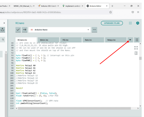
Can anyone type in the code how it’s suppose to be to control relay 16 when anyone of relays 1-13 are on? I was playing with the code a little bit, it just kept kicking it back at me. I would better understand if someone could type it in to see how the change affects operation. Am I suppose to change it in the relay section anyway or under that nano section?
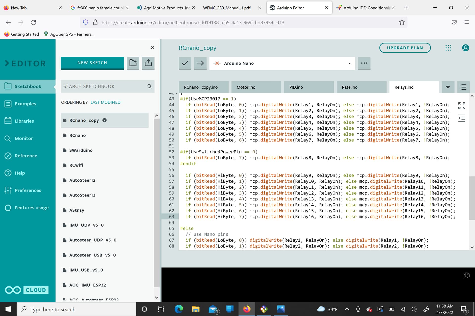
Also relay 8 doesn’t function, guessing because of the code using “switched power pin==0 stuff”? Is this suppose to be like this or should relay 8 look just like relay 1-7?
In the serialcomm.ino below line 108 add:
if (RelayHi > 0 || RelayLo > 0) RelayHi[7] = 1;
That should be close. @sk21 can verify.
It simply looks for anything on and then sets 16 to high.


look in here.