Motor wiring to prevent back feed Cytron

If the Cytron is not modified you have to remove the motor from the steering because it acts like an electric brake.

autosteer off + no cytron modification = electric brake effect, motor must be manually decoupled from steering, or powered off

autosteer off + modified cytron = freewheeling steering

As I said motor will generate some voltage when you turning steering wheel.
To generate 24v motor should be rotated at 588 rpm.
If boost converter used - output diode has enough strength to hold twice this voltage.
Without boost controller - voltage regulator on alternator should handle it (I did not test setup without boost converter).

But my NC Pin isn‘t anywhere connected (the red cable is not installed).
I use the old PCB Board from Autosteer.cc

What I have to do?

Would it be possible build in a Diode in each cable from the Motor to prevent the electric brake effect?

I am using 12 to 24v converter, no issues.

Using a diode on one of the motor cables will not allow motor to work on one of the directions. If you dont have the red cable, you can solder it from NC to Pwm2 in parallel to the black cable on above modification on picture from @PotatoFarmer, or green cable from @buched. Both are electrically the same point.

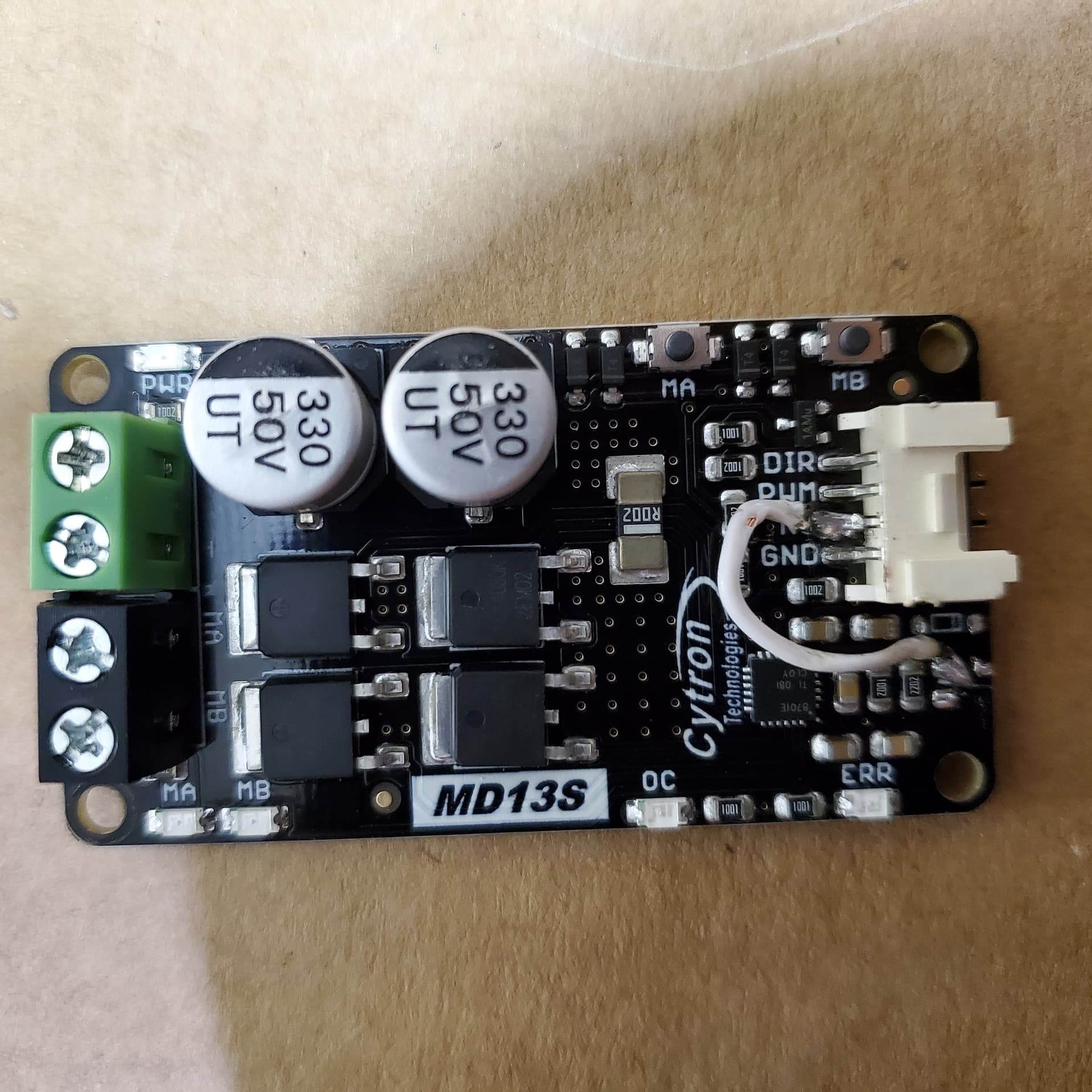
Hey Jussi did you ever get it to work? I’ve done 2 and they both didn’t work after. Could I have heated it too much when soldering? Maybe someone can spot the problem.

It looks good, we will wait for @Jussi reply.

Now that this is done it will not work unless it gets commanded by the Arduino to wake up. So the test buttons should not function unless its told to be awake at the same time.

It looks like the ones I am building.

1 Like

you put red wire on pwm2 ?

No. Red not used. Yellow to Dir1 white to Pwm 1 black to ground. Auto steer worked good till I did that mod.

The red from pwm2 is needed, it should get it working.

I think your welding is wrong.
Universal Fit Gear System, with Quick Tach Motor Holder - Hardware / Steering Mount files - AgOpenGPS

Either trace seems to work @buched has it working soldered there.

Ah ok will try that. Thought I had read somewhere it wasn’t needed. I see on your picture now you used it. Thanks

Hi! Yes, it worked for me like described by others. I haven’t yet had the time to install it to my tractor, but desktop setup works. I was confused in the beginning because the test buttons didn’t work anymore, but it doesn’t mean that in real life it wouldn’t work. When testing with the simulator, remember to put the steering on (steering wheel green in lower right corner).

1 Like

My mistake was not using the red wire. Works now.

1 Like

hello community

I’m starting my first adventure with AOG :grinning:.
Cytron md13s is not available in Poland.
How to modify cytron md20a to give free wheel? Someone has already done this?

Search the forum for free wheeling mod

Hi! Recently interested in AOG so replying to your thread back in 2021. I still can’t figure out the correct points to connect. You responded to the post (by Steigerguy) here being wrong (though PotatoFarmer indicated Steigerguy did it right) and provided a link to the correct one. I am putting the two images together below as well as a 3rd with high res image from the internet.

So the one on the left is the correct one and the one in the middle is wrong? So that is connecting NC with the encircled red will be the right connection? The two red X means what? Referring to the image on the right, so to prevent the cytron from applying a brake, soldering a piece of wire between NC and the rightmost leg of the resistor should do it? Thanks.

Both trace locations have been reported as functional

On the right picture the diode and resistor must be removed.