I did buy some Bno imus. I may need some help setting everything up, thanks for all the advice everyone.
for an excavator could i put imus on the machine and daisy chain all via Qwiic/i2c to an esp32 that is also connect to a f9p by i2c and the esp fuses the data for opengrade? and include all the math in the code? would agopengps be better for this with all its imu features? sorry for all the questions i have a lot to learn
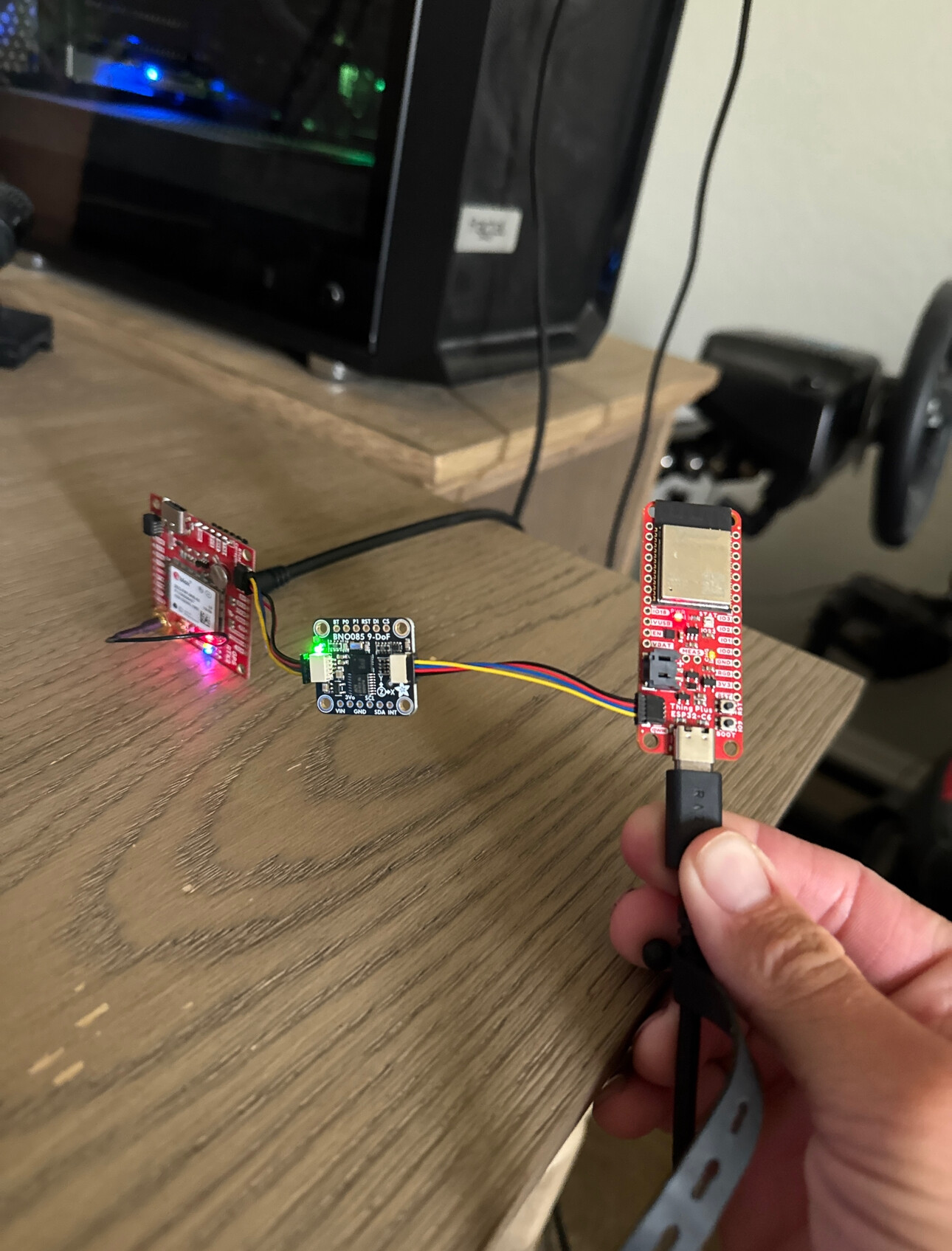
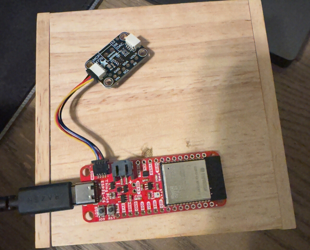
SparkFun Thing Plus - ESP32-C6 connected to a bno085 via i2c connected to a f9p via i2c
Maybe I should look more into teensy v4.2 that could be better and easier for what I’m trying to do.
I think I should be able to use these devices to fuse the data together to create a panda message for agopengps or opengrade
To test I think I should put my antenna on a pole and put the imu on the pole and see if it detects the tilt
I dont know how i would calibrate the bno and f9p to a pole or a machine. Maybe you put all the offsets in the code.
code I’ve been testing
#include <Wire.h>
#include <SparkFun_u-blox_GNSS_Arduino_Library.h>
#include “BNO08x_AOG.h” // Using the BNO08x_AOG library
// Constants and settings
const byte BNO08x_I2C_ADDRESS = 0x4A; // Default I2C address of the BNO08x
// Variables for IMU and GPS
BNO080 bno08x;
SFE_UBLOX_GNSS myGNSS;
float roll = 0, heading = 0, pitch = 0;
float latitude = 0.0;
float longitude = 0.0;
float altitude = 0.0;
int satellites = 0;
int fix_type = 0;
float hdop = 0.0;
String timeStamp = “000000.00”; // Placeholder for time
void setup() {
Serial.begin(115200); // Initialize Serial at 115200 baud
delay(100); // Allow time for Serial to start
Wire.begin(); // Initialize I2C communication
// Start the BNO080 with the specified I2C address
if (!bno08x.begin(BNO08x_I2C_ADDRESS, Wire)) {
    Serial.println("BNO08x not detected. Check wiring or I2C address.");
    while (1); // Halt execution if IMU is not detected
} else {
    Serial.println("BNO08x detected successfully.");
}
// Configure BNO080 for rotation vector (yaw, pitch, roll)
bno08x.enableRotationVector(25); // Set update rate to 40 Hz (or adjust as needed)

// Start the F9P (u-blox GNSS module)
if (!myGNSS.begin()) {
    Serial.println("F9P not detected. Check wiring or I2C address.");
    while (1); // Halt execution if GNSS is not detected
} else {
    Serial.println("F9P detected successfully.");
    myGNSS.setI2COutput(COM_TYPE_NMEA); // Ensure NMEA sentences are output over I2C
    myGNSS.saveConfiguration(); // Save the current configuration
}
}
void loop() {
// Get IMU data if available
if (bno08x.dataAvailable()) {
heading = -bno08x.getYaw() * 180.0 / PI;
roll = bno08x.getRoll() * 180.0 / PI;
pitch = bno08x.getPitch() * 180.0 / PI;
    if (heading < 0) heading += 360; // Adjust heading to 0-360 degrees
}

// Get GPS data if available
if (myGNSS.getPVT()) { // If a new PVT (position/velocity/time) data is available
    latitude = myGNSS.getLatitude() / 10000000.0;    // Convert to decimal degrees
    longitude = myGNSS.getLongitude() / 10000000.0;  // Convert to decimal degrees
    altitude = myGNSS.getAltitude() / 1000.0;        // Convert to meters
    satellites = myGNSS.getSIV();                    // Satellites in view
    fix_type = myGNSS.getFixType();                  // Fix type (e.g., 3D fix)
    hdop = myGNSS.getHorizontalDOP() / 100.0;        // Horizontal Dilution of Precision
    timeStamp = myGNSS.getTimeOfWeek();              // GPS time of week (optional)
}

// Build PANDA sentence
String pandaSentence = "$PANDA," + timeStamp + ",";
pandaSentence += String(latitude, 7) + ",N,";
pandaSentence += String(longitude, 7) + ",W,";
pandaSentence += String(fix_type) + ",";
pandaSentence += String(satellites) + ",";
pandaSentence += String(hdop, 2) + ",";
pandaSentence += String(altitude, 2) + ",,,";
pandaSentence += "276.6,";  // Placeholder Course Over Ground (COG)
pandaSentence += String(heading, 2) + ",";
pandaSentence += String(pitch, 2) + ",";
pandaSentence += String(roll, 2) + "*";

// Calculate PANDA checksum
int pandaChecksum = 0;
for (int i = 1; i < pandaSentence.length() - 1; i++) {
    pandaChecksum ^= pandaSentence[i];
}
pandaSentence += String(pandaChecksum, HEX);

// Build GGA sentence
String ggaSentence = "$GPGGA," + timeStamp + ",";
ggaSentence += String(latitude, 7) + ",N,";
ggaSentence += String(longitude, 7) + ",W,";
ggaSentence += String(fix_type) + ",";
ggaSentence += String(satellites) + ",";
ggaSentence += String(hdop, 2) + ",";
ggaSentence += String(altitude, 2) + ",M,,,";

// Calculate GGA checksum
int ggaChecksum = 0;
for (int i = 1; i < ggaSentence.length() - 1; i++) {
    ggaChecksum ^= ggaSentence[i];
}
ggaSentence += "*" + String(ggaChecksum, HEX);

// Output both sentences
Serial.println(pandaSentence);
Serial.println(ggaSentence);

delay(250); // Adjust delay to control update rate
}
Just thinking about hardware… I bet a wheel angle sensor on every join would be the most stable.
If OG was setup for dual antenna it would be easier to get a heading of which way the offset was going….
I think it would require going deep into the source code in VS code editor but I’m lost in there.
I wonder if I guy would study how roll compensation is done and inject an offset from that is sent to teensy by serial from an Arduino calculating the three “WAS” sensors right there.
1 Like
your not wrong WAS would be better and easier but i do want to try to learn more about imus. i want to add tilt compensation to a survey pole to learn how to fuse the gps and imu data together


here is some code ive been testing
code
#include <WiFi.h>
#include <WiFiClient.h>
#include <Wire.h>
#include “BNO08x_AOG.h” // Use the BNO08x_AOG library you confirmed works
#include “base64.h”
const char *ssid = “”;
const char *password = “”;
const char *ntripCaster = “”;
const uint16_t ntripPort = 2101;
const char *mountPoint = “”;
const char *username = “”;
const char *ntripPassword = “”;
// Adjust to your F9P’s I2C address
const int f9pAddress = 0x42; // Common default for F9P, but verify this for your setup
WiFiClient ntripClient;
BNO080 bno; // Create an instance of the BNO080 IMU
int bnoAddress = 0x4A; // Adjust if needed
// Calibration offsets (initialize to zero, update based on calibration)
float rollOffset = 0.0, pitchOffset = 0.0;
void setup() {
Serial.begin(115200); // For debug output
Wire.begin(); // Initialize I2C for F9P and BNO080
// Initialize BNO080 IMU
if (!bno.begin(bnoAddress, Wire)) {
Serial.println(“BNO08x not detected. Check wiring.”);
while (1); // Stop if IMU is not detected
}
bno.enableRotationVector(100); // Set IMU update rate to 10Hz
// Connect to Wi-Fi
Serial.print(“Connecting to WiFi…”);
WiFi.begin(ssid, password);
while (WiFi.status() != WL_CONNECTED) {
delay(500);
Serial.print(“.”);
}
Serial.println(“\nConnected to WiFi”);
// Connect to NTRIP caster
Serial.print(“Connecting to NTRIP caster…”);
if (!ntripClient.connect(ntripCaster, ntripPort)) {
Serial.println(“Failed to connect to NTRIP caster”);
while (true);
}
Serial.println(“Connected to NTRIP caster”);
// Send NTRIP request with Basic Authentication
String auth = base64::encode(String(username) + “:” + String(ntripPassword));
String ntripRequest = “GET /” + String(mountPoint) + " HTTP/1.0\r\n";
ntripRequest += "Authorization: Basic " + auth + “\r\n”;
ntripRequest += “User-Agent: NTRIP ESP32Client\r\n”;
ntripRequest += “Connection: close\r\n”;
ntripRequest += “\r\n”;
ntripClient.print(ntripRequest);
Serial.println(“Sent NTRIP request”);
// Check response from caster
while (ntripClient.available() == 0) {
delay(500);
Serial.print(“.”);
}
Serial.println(“\nNTRIP caster connection established”);
}
void loop() {
// Buffer to store incoming RTCM data for I2C transmission
uint8_t rtcmBuffer[32]; // Adjust buffer size if needed
int bufferIndex = 0;
// Read RTCM data from NTRIP and forward it to F9P over I2C
while (ntripClient.available()) {
rtcmBuffer[bufferIndex++] = ntripClient.read();
// If the buffer is full or the client has no more data to read, send it over I2C
if (bufferIndex >= sizeof(rtcmBuffer) || ntripClient.available() == 0) {
  Wire.beginTransmission(f9pAddress);
  for (int i = 0; i < bufferIndex; i++) {
    Wire.write(rtcmBuffer[i]);
  }
  Wire.endTransmission();
  bufferIndex = 0;  // Reset the buffer index
}
}
// Read and display NMEA data from the F9P over I2C
readAndPrintNMEA();
// Fetch IMU data
if (bno.dataAvailable()) {
float roll = bno.getRoll() * 180.0 / PI - rollOffset;
float pitch = bno.getPitch() * 180.0 / PI - pitchOffset;
float heading = bno.getYaw() * 180.0 / PI;
// Create the PANDA sentence with IMU and NMEA data
Serial.print("$PANDA,");
Serial.print(roll, 2);  // Two decimal places for roll
Serial.print(",");
Serial.print(pitch, 2); // Two decimal places for pitch
Serial.print(",");
Serial.print(heading, 2); // Two decimal places for heading
Serial.print("*CS"); // Replace with actual checksum if needed
Serial.println();
}
// Optionally, check if the connection was dropped and reconnect if necessary
if (!ntripClient.connected()) {
Serial.println(“Reconnecting to NTRIP caster…”);
ntripClient.stop();
setup(); // Retry connection by re-running setup
}
}
// Function to read and print NMEA data from the F9P over I2C
void readAndPrintNMEA() {
Wire.requestFrom(f9pAddress, 32); // Request 32 bytes from F9P (adjust if needed)
// Only read if there are available bytes
while (Wire.available()) {
char c = Wire.read();
Serial.print(c); // Print each character to the Serial Monitor
}
}
1 Like
An alternative to a WAS could be a draw wire sensor on the rams.
Machine control is something that I’ve been thinking about for a while but haven’t yet had time to do anything about it. However, when I was last pondering it I came across this work that analysed the difference between IMUs and draw wire sensors.
It is quite a good read - gives an overview of calculations and how they mounted the sensors to test the them, but the conclusion is basically that the draw-wire sensor is much better.
1 Like
i’ve been busy so i havent really had the chance to learn or try the code for my esp32 f9p bno till now. i need to modify the code a bit for it to work with ic2 and have it output the right nmea sentences for agopen. i feel like i could put f9p and ect on a pole connected to the bucket and it will tell me height and tilt, i’m not sure about heading or the right direction.
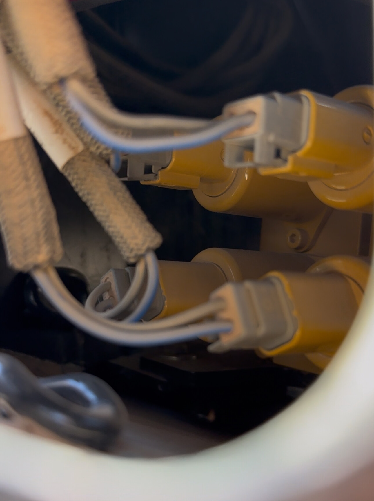
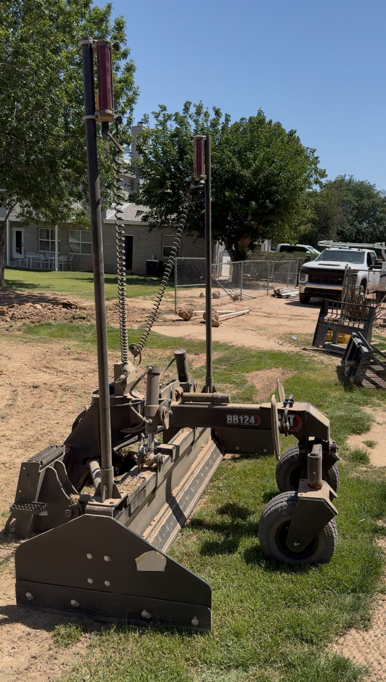
I just put the antenna on the bucket of my excavator. It does a good enough job for visual reference.
Sure it would be nice to put angle sensors but would be quite an amount of time to code.
Just be sure to have enough extension cable and spare SMA connectors. We had some antenna cables pinched, easy to put another connector. ![]()
3 Likes
I’d love to see some pictures of your setup. Yes all I really need is the elevation of the tip of the bucket. I could put an antenna on the bucket and use opengrade but I would have to keep it pretty level. I wonder if agopengps gives the right elevation with a imu and rover. Basically I’m looking for an open source way to have a tilt rover.
1 Like
I don’t know what i am doing and i could be doing all of this wrong so feedback is greatly appreciated. I want to learn how to use opengrade with a old danfoss valve I have.
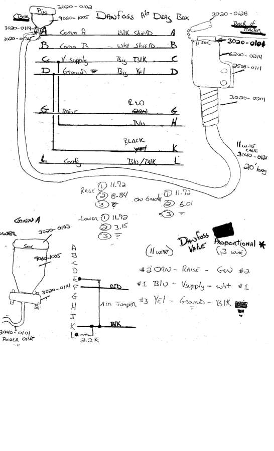
if i can figure that out i should be able to figure out how to get my new box blade attachment for my skid steer valves to auto grade.
For rovers I could use 2 emlid rs3 they will send tilt corrected nmea data to opengrade. since I can’t have 2 opengrades open on 1 pc i might have to use 2 pc for left and right side of the valves. not sure about pcb boards, I think i can use a esp32 to receive the up and down commands from opengrade, i think i would use a mosfet or a dac for voltage control to valves.
i am able to get blade control data from opengrade to the esp32 to the mcp 4725. I modified this code from Chris8960. here is the modified code,
// ESP32-C6 OpenGrade Serial Communication & RGB LED & MCP4725 DAC Control

#include <Wire.h>             // Required for I2C communication with MCP4725
#include <Adafruit_MCP4725.h> // Library for the MCP4725 DAC

#define SERIAL_BAUD_RATE 38400 // IMPORTANT: Match OpenGrade's baud rate!

// Built-in RGB LED settings (assuming ESP32-C6-DevKitC-1 compatibility)
#define RGB_BRIGHTNESS 64 // Adjust overall brightness (max 255)

// PGN (Parameter Group Number) definitions from the provided code
const int PGN_BLADE_CONTROL_DATA = 32762; // 0x7FFA - Data sent from OpenGrade to Module
const int PGN_SETTINGS_DATA = 32760;    // 0x7FF8 - Settings sent from OpenGrade to OpenGrade Module

// --- Variables for Incoming Data ---
int header = 0;
int tempHeader = 0;
bool isDataFound = false;    // Flag for PGN_BLADE_CONTROL_DATA
bool isSettingFound = false; // Flag for PGN_SETTINGS_DATA

// Values received from OpenGrade
volatile byte cutValve = 100; // This is the 0-200 vertical error value (100 = on target)
volatile byte bladeOffsetIn = 100; // Blade offset value from OpenGrade

// --- Variables for Outgoing Data (Feedback to OpenGrade) ---
// These need to match the type and content expected by OpenGrade.
// For this example, we'll use placeholder/default values as we don't have
// actual sensor inputs or full control logic implemented here.
int pwmValue_out = 0;       // Placeholder for output PWM value for blade (negative for lower, positive for lift)
byte bladeOffsetOut = 100; // Our module's calculated blade offset (100 = 0 offset)
float dfValue_out = 0.500;  // Placeholder for danfoss valve value (e.g., 0.0-1.0)
float pwmValueCalc_out = 0.0; // Placeholder for internal PWM calculation value
int pwm_out = 2048;         // Placeholder for DAC value (e.g., 0-4095 for 12-bit DAC)
float pwmHist_out = 0.0;    // Placeholder for PWM history/derivative component

// Loop timing (simulating the original code's 20Hz loop)
const byte LOOP_TIME = 50; // 50 ms = 20 Hz
unsigned long lastLoopTime = 0;

// Watchdog timer for communication health
byte watchdogTimer = 0; // Increments, reset when data is received
const byte WATCHDOG_TIMEOUT_LIMIT = 30; // Roughly 30 * 50ms = 1.5 seconds without data

// --- MCP4725 DAC Setup ---
// Adafruit_MCP4725 dac; // If you're using the default address 0x62
// Or, if your A0 pin is tied high (0x63):
Adafruit_MCP4725 dac; // Default I2C address for MCP4725 is 0x62 (or 0x60/0x64 depending on chip suffix)
                      // The Adafruit breakout defaults to 0x62. If you connected A0 to VCC, use 0x63.

// Define the maximum digital value for the 12-bit DAC
const int DAC_MAX_VALUE = 4095; // 2^12 - 1

// Define the DAC's actual supply voltage (VCC), which determines its output voltage range
// Set this based on how you are powering your MCP4725 breakout board!
// If from ESP32 3.3V pin:
const float DAC_SUPPLY_VOLTAGE = 3.3;
// If from external 5V source:
// const float DAC_SUPPLY_VOLTAGE = 5.0;


void setup() {
  Serial.begin(SERIAL_BAUD_RATE);
  Serial.setTimeout(50); // Set a short timeout for Serial.read() if needed

  // Initialize I2C for the DAC
  Wire.begin();
  if (!dac.begin(0x62)) { // Try default address 0x62 first
    Serial.println("Error: Could not find MCP4725 DAC at 0x62!");
    // You might try 0x63 if you tied A0 high, or 0x60 for some other chips.
    // For now, halt if not found, as DAC is critical for output.
    while (1) delay(10);
  }
  Serial.println("MCP4725 DAC found and initialized at 0x62!");


  // Initial LED feedback to show startup
#ifdef RGB_BUILTIN
  rgbLedWrite(RGB_BUILTIN, 0, RGB_BRIGHTNESS / 2, RGB_BRIGHTNESS / 2); // Faint cyan on boot
  delay(1000);
  rgbLedWrite(RGB_BUILTIN, 0, 0, 0); // Turn off after 1 sec
#endif

  Serial.println("ESP32 OpenGrade Communication & LED & DAC Demo Started.");
  Serial.print("Baud Rate: ");
  Serial.println(SERIAL_BAUD_RATE);
  Serial.print("DAC Supply Voltage set to: ");
  Serial.print(DAC_SUPPLY_VOLTAGE);
  Serial.println("V");
}

void loop() {
  // --- Timed Loop (similar to original code's 20Hz loop) ---
  unsigned long currentTime = millis();
  if (currentTime - lastLoopTime >= LOOP_TIME) {
    lastLoopTime = currentTime;

    // Increment watchdog timer. If it goes too high, assume communication lost.
    if (watchdogTimer++ > WATCHDOG_TIMEOUT_LIMIT) {
      // Communication lost with OpenGrade
      Serial.println("Warning: OpenGrade communication lost! Setting cutValve to 100 (idle).");
      cutValve = 100; // Default to on-target (no movement) for safety
      watchdogTimer = WATCHDOG_TIMEOUT_LIMIT + 1; // Cap it to prevent overflow and repeated messages
    } else if (watchdogTimer == 0) {
      // This means data was received and watchdog was reset in the serial parsing section
    }

    // --- Update RGB LED based on cutValve ---
#ifdef RGB_BUILTIN
    updateRgbLed(cutValve);
#endif

    // --- Control Danfoss Valve via DAC ---
    // This is where you map the cutValve (0-200) to the DAC output range (0-4095)
    // and then to the Danfoss valve's expected input (2.2V to 11.72V)
    // For this demonstration, we'll map cutValve 0-200 to DAC 0-4095.
    // In a real application, you'd use your full PID logic (SetPWM function)
    // and then apply the external amplifier.

    // Map cutValve (0-200) to pwm (0-4095)
    // A cutValve of 100 is neutral. Let's make it map to the middle of the DAC range (2047.5).
    // A cutValve of 0 (lower) maps to 0. A cutValve of 200 (raise) maps to 4095.
    // This is a simple linear map for demonstration. Your actual PID logic will replace this.
    int dac_value = map(cutValve, 0, 200, 0, DAC_MAX_VALUE);
    dac.setVoltage(dac_value, false); // Send the digital value to the DAC (false = don't store in EEPROM)

    // Calculate the expected analog voltage output from the DAC for monitoring
    float expected_dac_voltage = (float)dac_value / DAC_MAX_VALUE * DAC_SUPPLY_VOLTAGE;

    Serial.print("DAC Output - Raw Value: ");
    Serial.print(dac_value);
    Serial.print(", Expected Voltage: ");
    Serial.print(expected_dac_voltage, 3); // Print with 3 decimal places
    Serial.println("V");


    // --- Send Feedback to OpenGrade (Heartbeat / Status) ---
    // This is the critical part that tells OpenGrade we are alive and ready.
    sendFeedbackToOpenGrade();
  }

  // --- Continuous Serial Data Reception (outside the timed loop) ---
  // This section should run as fast as possible to catch incoming bytes.
  parseIncomingSerialData();
}


// --- Function Definitions (from previous code, unchanged) ---

void parseIncomingSerialData() {
  while (Serial.available() > 0) {
    int currentByte = Serial.read(); // Read one byte at a time

    header = (tempHeader << 8) | currentByte;
    tempHeader = currentByte;

    if (header == PGN_BLADE_CONTROL_DATA) {
      if (Serial.available() >= 6) {
        cutValve = Serial.read();
        bladeOffsetIn = Serial.read();
        Serial.read(); // optOut1
        Serial.read(); // optOut2
        Serial.read(); // optOut3
        Serial.read(); // optOut4

        isDataFound = false;
        watchdogTimer = 0;

        Serial.print("RECEIVED - CutValve: ");
        Serial.print(cutValve);
        Serial.print(", BladeOffsetIn: ");
        Serial.println(bladeOffsetIn);
      }
    }
    else if (header == PGN_SETTINGS_DATA) {
      if (Serial.available() >= 8) {
        for (int i = 0; i < 8; i++) {
          Serial.read();
        }
        isSettingFound = false;
        watchdogTimer = 0;
        Serial.println("RECEIVED - Settings PGN (read and discarded for demo).");
      }
    }
  }
}

void sendFeedbackToOpenGrade() {
  if (pwmValue_out < 0) {
    Serial.print("1,");
  } else {
    Serial.print("0,");
  }

  Serial.print(abs(pwmValue_out));
  Serial.print(",");
  Serial.print(cutValve);
  Serial.print(",");
  Serial.print(bladeOffsetOut);
  Serial.print(",");
  Serial.print(dfValue_out * 5);
  Serial.print(",");
  Serial.print(pwmValueCalc_out);
  Serial.print(",");
  Serial.print(pwm_out);
  Serial.print(",");
  Serial.println(pwmHist_out);

  Serial.flush();
}

void updateRgbLed(byte val) {
#ifdef RGB_BUILTIN
  uint8_t red_val = 0;
  uint8_t green_val = 0;
  uint8_t blue_val = 0;

  if (val >= 0 && val <= 200) {
    if (val == 100) {
      red_val = 0;
      green_val = RGB_BRIGHTNESS;
      blue_val = 0;
    } else if (val < 100) {
      blue_val = map(val, 0, 99, RGB_BRIGHTNESS, 0);
      green_val = map(val, 0, 99, 0, RGB_BRIGHTNESS);
      red_val = 0;
    } else { // val > 100
      red_val = map(val, 101, 200, 0, RGB_BRIGHTNESS);
      green_val = map(val, 101, 200, RGB_BRIGHTNESS, 0);
      blue_val = 0;
    }
  } else {
    red_val = RGB_BRIGHTNESS / 4;
    green_val = RGB_BRIGHTNESS / 4;
    blue_val = RGB_BRIGHTNESS / 4;
  }

  rgbLedWrite(RGB_BUILTIN, red_val, green_val, blue_val);
#endif
}

// Dummy/placeholder functions from original code to allow compilation
void SetPWM() {}
void SaveToEEPROM() {}
void ReadFromEEPROM() {}
with this i only get about 3.3v from the mcp, i need to learn how to amplify voltage to get around 9v to fully use my danfoss
That chip only goes up to 5.5v max
Your right. I have the the MCP connected to the esp via a qwiic stemma cable. The esp is connected to the pc via usb. Right now the MCP is only outputting 0v-3.3v. What would you recommend I do to get the 3v-9v I need to control the Danfoss?
Do I learn how to amplify voltages?
Do I try to find a device that takes pmw from esp and then outputs 3v-9v?
Just curious it possible to supply 5v to the MCP from the esp32 qwiic cable?
Thanks
Can you edit the code above with triple backticks before and after search backtick for your keyboard. iOS Hides it pretty good.
begin
1 Like
I’m not sure how much ChatGPT modified chris code to work with my esp. I added some code so the esp on-board led light would change color corresponding to the cut value opengrade3D
I don’t know if esp code have the Danfoss conversion already.
But maybe check teensy code to find what settings are charged when selecting Danfoss in AOG autosteer program. To find what is needed for grade control.
Here is a Video of opengrade3D outputting 0v-3.3v
You can take a look to the teensy firmware and PCB V4.5 board, which supports danfoss via PCB V4.5 board
    if (steerConfig.IsDanfoss)
    {
        // Danfoss: PWM 25% On = Left Position max  (below Valve=Center)
        // Danfoss: PWM 50% On = Center Position
        // Danfoss: PWM 75% On = Right Position max (above Valve=Center)
        pwmDrive = (constrain(pwmDrive, -250, 250));

        // Calculations below make sure pwmDrive values are between 65 and 190
        // This means they are always positive, so in motorDrive, no need to check for
        // steerConfig.isDanfoss anymore
        pwmDrive = pwmDrive >> 2; // Devide by 4
        pwmDrive += 128;          // add Center Pos.

        // pwmDrive now lies in the range [65 ... 190], which would be great for an ideal opamp
        // However the TLC081IP is not ideal. Approximating from fig 4, 5 TI datasheet, @Vdd=12v, T=@40Celcius, 0 current
        // Voh=11.08 volts, Vol=0.185v
        // (11.08/12)*255=235.45
        // (0.185/12)*255=3.93
        // output now lies in the range [67 ... 205], the center position is now 136
        //pwmDrive = (map(pwmDrive, 4, 235, 0, 255));
    }
May be this helps.