Hello,
I’m currently assembling an autosteer system. Got the Kaupoi PCB pre assembled and pretty much all the tools.
I have a very noob question: I’m sorry if it sounds stupid, but I’m very new to Ago and I couldn’t find any topic that would clear the confusion in my mind, as most of the threads are too advanced for me.
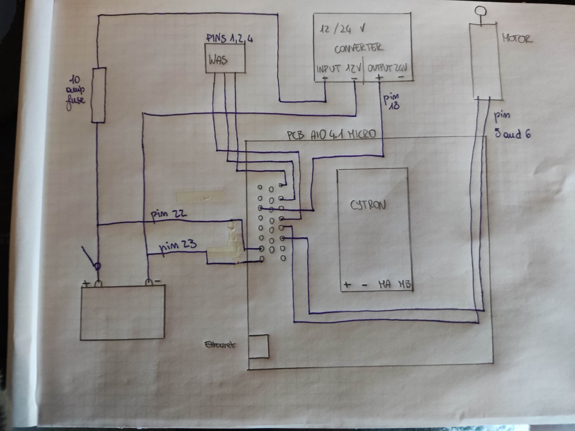
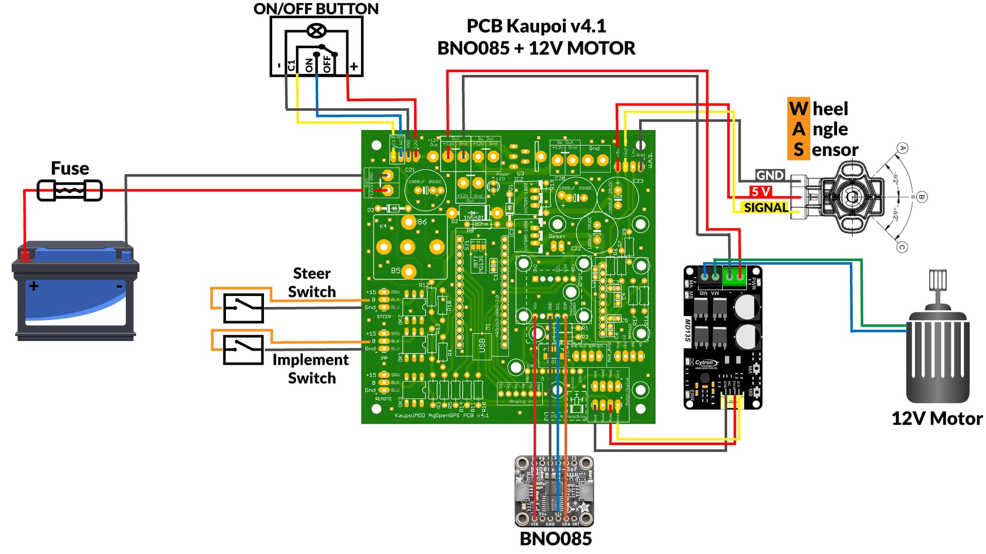
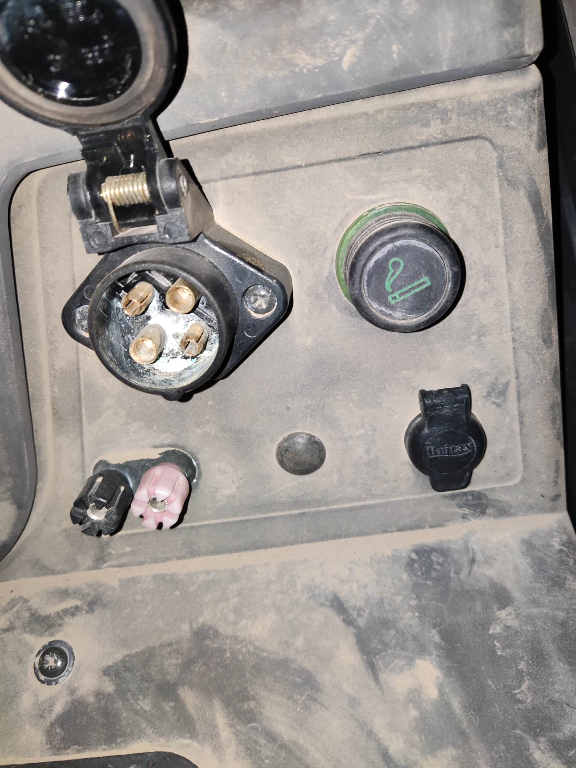
I am assembling my PCB according to the scheme in the first pic. I had everything sorted out, I thought. Problem is now battery connection: according to the scheme I need only 2 wires (12V and Gnd) to be attached to the connector through which I would supply power. When I go to the Github page however I saw the second picture, that shows that the main connector has to ‘receive’ many cables, including (see picture 3) for instance Was wires, which I thought had to be connected to the PCB, or the autosteer switch cables, which again I thought had to be connected to the PCB, according to the first picture.
Can someone explain what I am getting wrong?
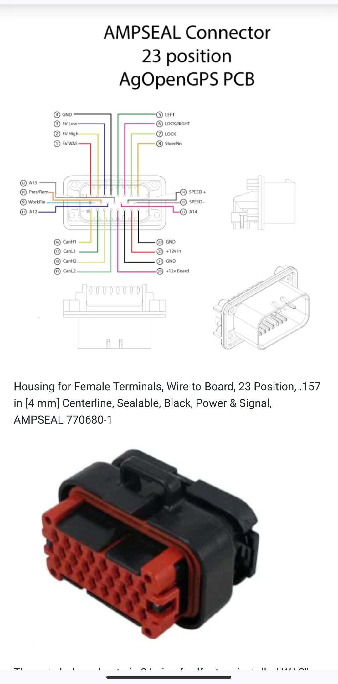
The ampseal connector is really designed for use with the All-In-One board, not Kaupoi.
Nothing to stop you using one of course, but there’s no mount plate for it on the board.
You can wire direct as per your first image, and ignore the ampseal totally if you wish.
Thank you so much. This is really great news. Thank you very much Sir
Ok, I got the wec and the motor mounted on the steering wheel. In the meanwhile that I receive the gears I have one more question. Still need to supply power to my PCB. I need to use the autosteer on 2 tractors (new holland tm125 and massey ferguson 390t). These are the sockets I have in both of them. Can’t remember where but I read that I need to apply a 10ampere fuse to the power line. Does anyone know which one is suitable to provide the right voltage/amperage to power the pcb. Also, which technical specs should I look for in the fuse? 12 volts 10 ampere I guess?
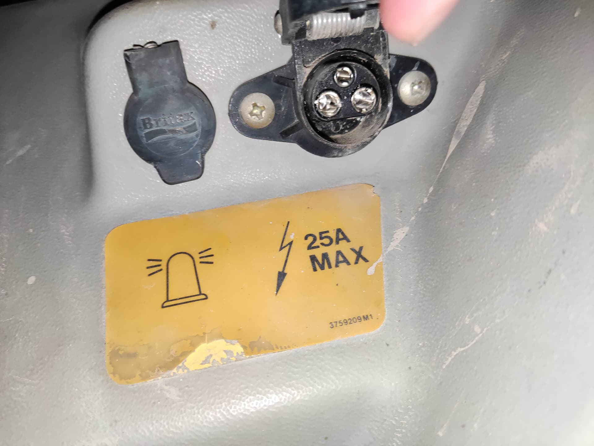
Confirm your outputs with multimeter, but 12V as illustrated
Thank for answering. As for the the first pic something like this in the cigar lighter socket should work right? I would just need to connect the wires with the ones coming out of my PCB box I guess
Hi Gascio! Glad you were able to resolve your confusion and able to implement agopengps. I have successfully populated my AIO microv4.1 board. I am now focusing on wiring my setup and have been all over the place and posting along the was requests for assistance. And then I saw your third picture! That’s the one I’ve been looking desperately. Can you tell me the web address where you got it? Many thanks.
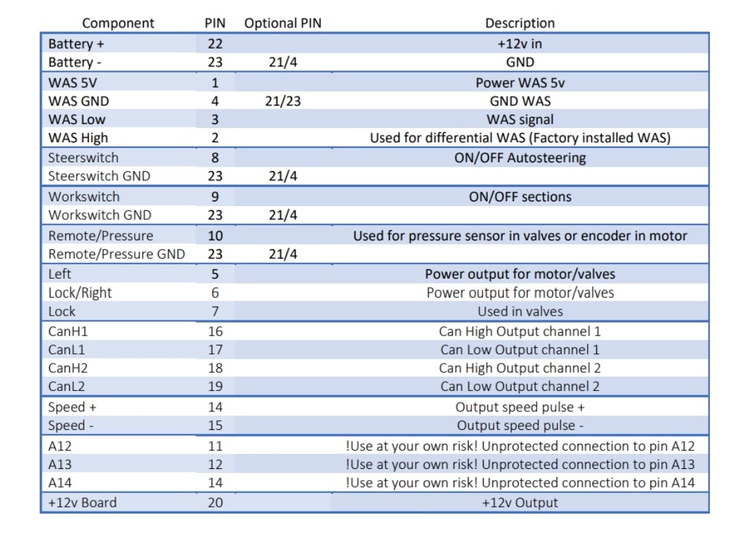
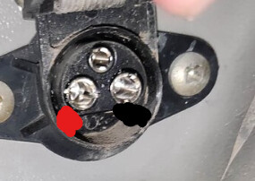
I don’t remember where I took that specific pic, but Here you can find the list of the ampseal pins. As for the was, the ampseal can receive both 3 and 4 pins sensors. If your was is a 3 pin one, you should use
Pin 1 ampseal: 5v
Pin 2 ampseal: signal
Leave pin 3 unused
Pin 4 ampseal: gnd
Also: you might be interested in this picture. This is the sceme I used for my micro4.1. Bear in mind however that I used a 24v converter to power my motor. If you use 12v it’s different