Are you using Cytron + Kaupoi 4.1?
under the arduino the pads are inverted, take a look.
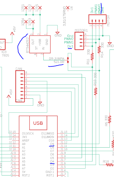
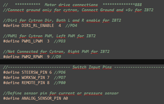
I use Kaupoi 4.1 with cytron. Now check the panel: Cytron’s pwm is on pin D9 on the board, this is pwm2. I have cryton’s pwm connected to Kaupoi pwm1. Transfer the cytron’s pwm to Kaupoi pwm2. Or do I need to override the code? If I need to fix code, what should I rewrite?
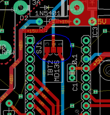
with that you invest that activates and deactivates, how do you have it soldered?
1 between 2, cytron
it’s inverted, just weld to the other side
USE 3-2 for Cytron
USE 1-2 for IBT2
Do you have a picture of where you connected the sensor?
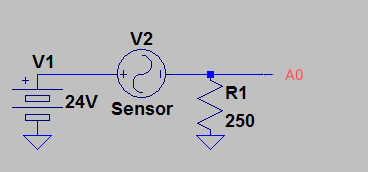
I connected D4 pin- (cytron)Dir and (Bts)2 pin. D3 pin (cytron) pwm. Thus, the Bts442 is permanently switched on, it continuously receives a 5v signal on pin two. And it gets very hot. the 6/2 valve takes a current of 2.65 A.
BUT d4 is only 5v to one side/half the time, when set to cytron.
My 6/2 use about same amperage, but I use a relay ,because I still have a PCB ver 1.
Does the 442 stay on in your 5 v test, or does it shut down once in while to cool off. It will turn on automatically when cold enough.
Perhaps add a cooler finn to it.
I gave up the fight with Bts 442😂. I converted it to relay switching. It worked without a problem today.
Since I converted it to relay switching, it has been working well. The problem was with bts.
You may get to the point, where relay get burnt at connection points inside. I changed my cheap Chinese arduino relays with a l298n motor driver, ( which I had at hand) that activate 12 v automotive relay. Have not yet tried l298n direct to valve, but this should be possible according to possible constant load on l298n.
I control an automotive relay with the ardunio relay. But then I will convert it to a LR7843 mosfet control. The power supply on the panel is actually low for BTS