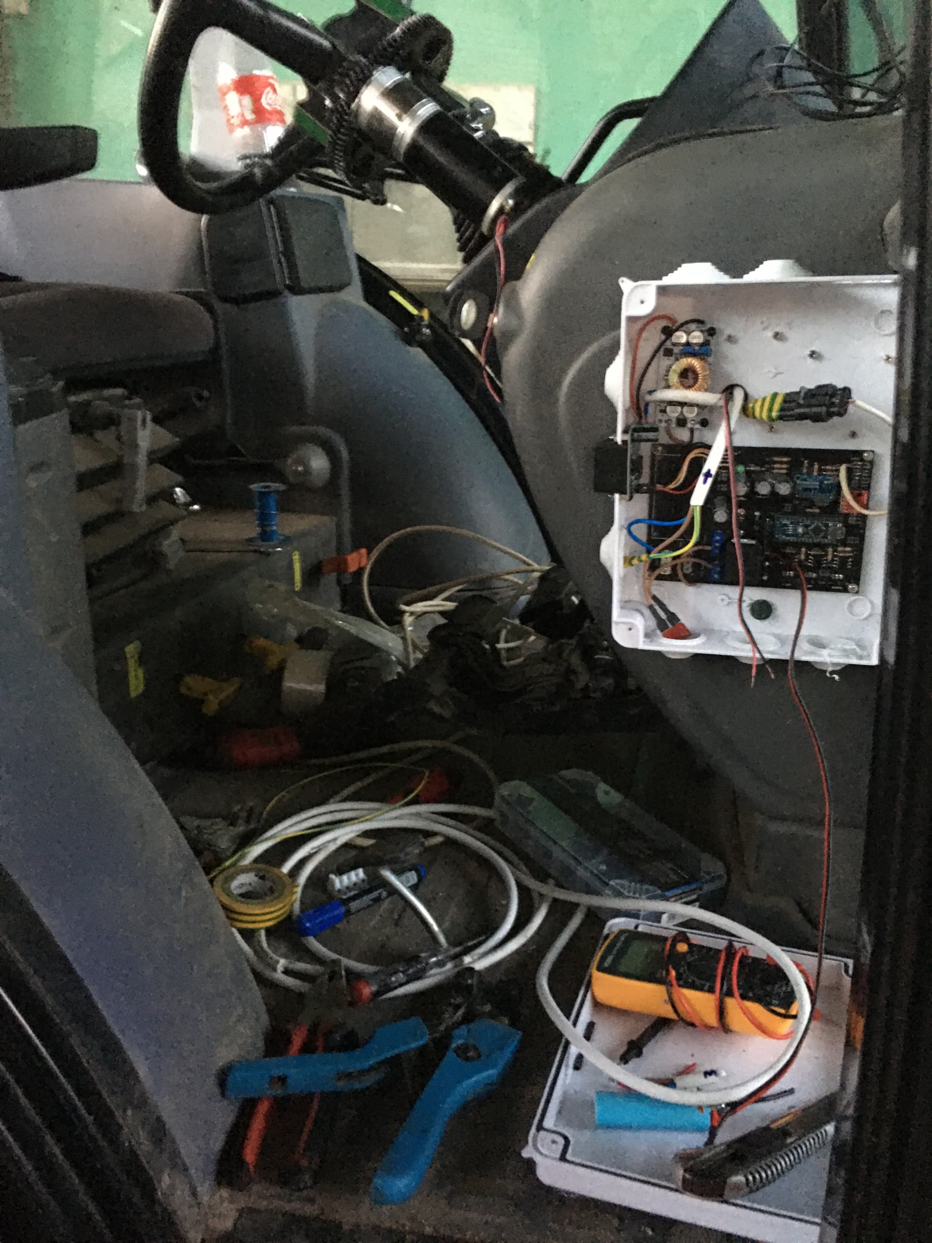
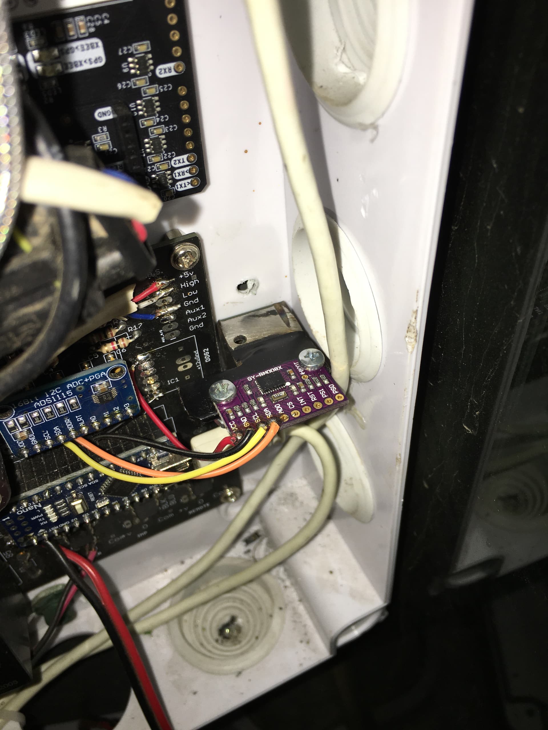
Hello everyone, ive been seeding these couple of days with AOG v5.2, and its amazing, but i noticed my BNO lies about its roll probably because the BNO is located on the right side of the steering wheel in a box with everything else, so i have decided to put the BNO with a spare arduino on the pivot point of the tractor and i want to put it in a 3d printed box, the problem is im not familliar with 3D moddeling so if anyone has a STL file that they would like to share i would be very thankfull. The picture below is for reference (when i was putting it together)
Hello, are these things suitable for you?
These came up in my mini enclosure searches.
2 Likes
Thanks, i will try it
What is happening that you think the data is bad?
Its tough to picture but right, left, or in the middle the gyro should read the same. Think of a level on a ramp. The bubble will read the same at the very top or bottom of the ramp if the slope is the same.
Well when the tractor is on a hill it goes sloppy, messes up a perfect line. Also i noticed going on the hill one way the IMU reads +4 degrees, going back on the same hill it reads -7 degrees. My antenna is 272cm above ground on top of the cabin, so im thinking the IMUs bad reading is at fault for the zigzag.
I had that same feeling of zigzag, first I once more zeroed roll and got equal reading both directions. That didn’t help so tried longer fix to fix distance and more imo than gps. I think the problem is the lag from roll time to calculations are done (and very visible on uneven ground). At the end I just set antenna hight to zero m, to eliminate roll influences on steering. That made steering straight, even quite nicely on shifting slopes, because when tractor roll to left, it must steer uphill to keep antenna on line, while seeder in hitch drag about as much downhill.ø
When you have different roll readings on same hill, AOG will move the line (based on the antenna hight) unequal distance to the side, going opposite direction.
I use bno085 directly on steering PCB, perhaps calculations come faster if bno085 is on separate PCB (has its own com port.
On the roll setup page try turning the roll filter much lower to less, like 10 instead of 50. Then slowly turn it up over a couple trips.
Make sure the + and - tilt are like the picture.
+4 vs -7 degrees is an extremely small measurement, one of your tires could be a little low, or true zero is -2. Neither I would worry about.
True, filtering makes the problem bigger. And you can compensate a non zero (incorrect) roll by implement offset.
Hmm, i will try to zero the antenna. I also tried changing the fix to fix distance (currently 2,5m) that helped a little bit, also tried changing the roll filter and the imu GPS percentage it didnt help at all.
The + and - of the roll are set correctly as per picture. Tires are equal, already checked. I set the zero offset on straight concrete. As you can tell from the picture i posred the bno is set on the right side of the tractor in box thats why it lies about the roll.
When you have zero roll, no matter what direction tractor is pointing on your flat concrete. Then I will ask: is your bno085 fully parallel to driving direction. (If not parallel then nose down could show as a little roll. )
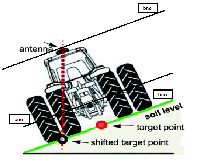
The height or the position of the BNO along the black lines will not matter, even if it is 2m outside the cab it will still read the same angle.
How the software calculates the shifted point, and how aggressively it corrects for it does.
4 Likes
I just checked it is not fully parallel. Its a little bit off to the left.
Okay i understand now. My main concern is the zigzag line thing it does, so i changed the antenna height to 0 as @Larsvest suggested, i will test it as soon as i can. @PotatoFarmer can you explain to me what the roll filter does, will it eliminate the offset im having.
if (ahrs.isRollInvert) rollK *= -0.1;
                            else rollK *= 0.1;
                            rollK -= ahrs.rollZero;
                            ahrs.imuRoll = ahrs.imuRoll * ahrs.rollFilter + rollK * (1 - ahrs.rollFilter);
From playing with it I felt less filter meant less correction was added.
I tracked it down in the code an it looks like that is exactly what it does, I am trying to learn about AOG under hood on the PC. So it takes the raw roll from the BNO and enhances to be bigger or smaller than reality then places it in the variable ahrs.imuRoll once there it goes to a new piece of code with the antenna height to figure out where your hitch is.
if (ahrs.imuRoll != 88888)
                                {

                                    //change for roll to the right is positive times -1
                                    rollCorrectionDistance = Math.Tan(glm.toRadians((ahrs.imuRoll))) * -vehicle.antennaHeight;

                                    // roll to left is positive  **** important!!
                                    // not any more - April 30, 2019 - roll to right is positive Now! Still Important
                                    for (int i = 0; i < 3; i++)
                                    {
                                        stepFixPts[i].easting = (Math.Cos(-gpsHeading) * rollCorrectionDistance) + stepFixPts[i].easting;
                                        stepFixPts[i].northing = (Math.Sin(-gpsHeading) * rollCorrectionDistance) + stepFixPts[i].northing;
                                    }
                                }
Since the roll filter is in place, before the actual calculation of the hitch location it is a very potent setting.
so how to look at it would be. (Roll Filter x Raw BNO ) x hitch postition math + gps location)= where the tractor thinks it actually located.
It takes awhile to get everything tuned in, what is the biggest offline number you see on flat ground?
The most powerful oscillators to get tuned in AOG are; Steering Angle, PP Look ahead, Roll Filter, WAS zero, Low Motor speed, and Min motor speed.
Guess that is why I couldn’t find out to use roll. I believed more filter reduced influence from roll.
Exactly, lots of the settings make me question that as well. There is no clear bigger means result wording in the manual quite yet.
I was meaning to ask about steering angle, in the tractors book that came with the tractor it says the max steering angle is 40 but AOG calculated CPD and anckerman to equal to 30 degrees steering angle, i don’t really care as long as it goes straight, it is just something interesting i noticed.
Also i don’t understand what the low motor speed does. The min is set to almost turn the wheels.
1 Like
https://discourse.agopengps.com/t/another-easy-way-of-determining-steer-angle/7391/2
Steering angle is the the angle of the inside wheel in a turn. The drive in a circle method does not always work properly. If you can physically measure it, and sometimes find it in the tractors manual(which you did!!!). The method with the phone app works well too.
Drive forward straight by hand as good as you can, aiming at a close tree or post helps, press WAS 0
Once you have the measured angle (40) crank your wheels to the right and hold, adjust counts per degree so the was angle matches your determined steering angle. Then crank all the way to the left, use ackermann to make the left (40) equal the right (40).
Then max steer set 1-2 degrees below the steer angle so you don’t hit your stops.
Min Motor speed is the minimum commanded to make the motor move, good place to start is 22
too low the motor never shuts off and gets hot, too high you drift offline before anything can happen.
Low motor is the speed that small offline corrections are made at, if this is too high you will overshoot the AB every time it steers to low you take forever to correct back to the line, Good place to start is 44.
High motor speed is the max rate it can command especially in uturn, it needs to be fast enough to keep up with the turn but not so fast you whip. Good place to start is 190.
P(roportional) is the multiplier for your error offline. Ive always left it on 102, values between 80-120 do not seem to do much for me. How i set this is by looking back at my row, if i can see jogs in the line its too high so I lower it until it looks smoother, very last setting touched.
Look ahead is very important 2.4 is a great place to start, turn it up till you wiggle, turn it down and you wiggle, you will notice a sweet spot in the middle.
Not sure look ahead speed gain does to much but too leave it at 1.4
side hill degree per degree of roll start with 0, move up very slowly, helps automatically turn a little up hill on sidehill.
Integral use the bare minimum you need, this is a last chance to keep you on a slope. Start with 2, slowly adjust up if having slippery slope issues. the number above the PP button shows if Integral is active and by how much.
7 Likes
Thank you all for your help, i will fine tune my autosteer with this. Regarding to setting the CPD and anckerman i already tried it like you explained and it was horrible it goes off the line, basicly drives like its drunk, so i will leave it like it is.