Account for reduced effective tool width at side hill

Preface:

Correct track distance even on hill slope of > 25 % was one of the expectations for me to go for cm-level RTK. Running an organic farm, with the option of hoeing most of the crops, this were a game changer.
To learn that it’s not yet built into AOG is not far from being a game-stopper for me.

When a machine is tilt around the roll axis, effective work with as seen from top (what the current state of AOG art does) shortens by cos of the roll angle.

To illustrate the math, I drafted this chart:


As we see, for relevant angles, slope in percent (aka tangens) grows nearly linearly with roll angle, while the shortage of work width, given as 1-cos(roll), grows approximately with square rate.

1 Like

I’ve started discussion of the topic at the Telegram Lounge, but there it get’s buried under all other topics. So, for reference, I’ll replicate the essence here:

How (if at all) does AOG take account of the reeduced working widht of an implement at side hills?

I’m well aware that the notion of “side hill” is subject to the principle of relativity.
Even in the intro videos of AOG, 8% is reportet as “side hill”, which I’d consider as “nearly flat”

Let’s look e.g. at my seeder, 6 m in width, organic farming with mechanical weeding by hoe.
Seed row spacing is 21 cm.
At 5 deg ~ 9 % side hill, the error is ~ 2cm, on par with excepted RTK error - fine.
At 8 deg ~ 14% side hill , the error is 1% ~ 6cm - still acceptible in my eyes.

at 10 deg, ~ 18 %, the error is 9 cm - not far from half a row missing.
Hoeing starts to leave unprocessed strips - not fine.
This is when my (lately burned) MF 38 Autolvel combine hit it’s balancing limit.
As far as I remember, this happened at ~ 50 % of my fileds.

Max side hill I have to deal with is ~ 20 deg, ~~ 35 %.
Error in width is 6 % then - 36 cm - more than 1 1/2 seeding rows missing :exploding_head:.


Answer of Patrick Imhof:
2D only, doesn’t account for this.


've been afraid of that… :cry:
What where required to do so, or at least to work aorund?

The precise solution would be to keep track of the last edge, which is away from last center line by
half machine width * cos( last roll),
and ride at new centerline, offset from said edge =
half machine width * cos (current roll).

But for that, I had to delve into the source, I’m afraid.
Might you just give me some pointer where to start descending the rabbit hole?


A workaorund outside of AOG would be to prepare the map offline, with the help of some digital elevation model.
Is there a way to load such a map of tracks (not only perimeter or single guide lines) into AOG and have the steering follow them, then?

… or I might just add some constant nudging?
E.g. at 14 deg roll ~ 25 % slope, when I nudge by 18 cm, ±2 deg roll change result in ± 5 cm track error.
Better than my current manual driving, at least…

I’ve checked this idea with my fields, and find that expected errors remaining are within a reasonable level.
So at least, I’ll not stop AOG implementation at this point.


This is about half of the area under my plough.

As you can see, the middle and the south can be worked close to contour line, which eases the application of constant nudging.

[ Lars ]
Don’t forget that most of the"fault" is due to the ground have more meters when on a hill(compared to level field). So if you try to correct that your ab lined will not be straight.


Of course.
In the field to the north of above map, sometimes even at manual steering, I’d cut the Line and start afresh with a new one.

Next I tried to head for an offline preparation of a track map.

The public land surveying office in Bavaria offer a digital elevation model (aka DEM) in 1m an 5 m resolution, both as geo-TIFF and as ascii-XYZ-file.

First I tried to import the 1m Geo-Tiff into QGis.
Looks nice, but not sure how to proceed from here.

At least we see that the whole picture is quite smooth, so a 1m resolution might be overkill.

Next I imported the 5m-XYZ DEM-data into FreeCAD.
Regarding the nerdy wisdom that the algorithm is 5 % of the work, the user interface 95 %, a full fledged 3D-GUI might come handy.

Convert it to a “structured point cloud” and tesselation to a triangulated map looks like this:

Then I’ve cut the DEM by a vertical plane, resembling a straight (in top view) AB line to start (or meet in the middle, or whatever).
Next I generated a “tube” around this line and calculate the intersection of this tube with the DEM again, resembling an equidistant line measured along hill slope.

From the side, this is what it looks like:


The middle black line is the intersection of a straight AB with the DEM.
The outer black lines are parallel shifts of the middle by machine width, as AOG in current stage might produce it.
The green lines are the intesection of the tube with the DEM - where the correct next track would be, considering the hill slope.

In top view, at sufficient zoom, the expected difference between 2D-simplification and correct 3D solutiom becomes clearly visible.

Thus I’d consider to have delivered proof of concept, at least.
However, I could not manage to repeat these steps, computational requirements are horrific, and at a close look you might see level white lines - artefacts of unknown origin.

So I think it might be a better idea

  • to work in 2D and just apply a correction by local cos(roll)
  • to simplify the curves at every iteration to keep computing requirements in bounds
  • to go as close to metal as possible, i.e. using high performance math libs as available in python e.g.

Of course, best would be not to reinvent the wheel but find some work to build upon.

Any ideas?

I’m not aware of a single commercial auto-steer tool taking slope into account and adjusting waylines accordingly. This means there must be very little interest for this approach. In any case, it is an interesting challenge.

Most machines work best when driving straight, this is why we pretty much always pick up a straight A-B line for most of the field and do only headlands with contour lines. On a steep field I would select a wayline that has the least possible change of side slope and just use sufficient overlap to get the field 100% covered (if you prefer no missed area).

I don’t think it is a good idea using the previous wayline as a reference and take the current slope into account when calculating the next wayline. Errors accumulate and you’ll end up with odd curves too. You could not drive every second wayline to make u-turns easier etc. You could not move hay with an asymmetric mover.

I feel the only sensible approach would be to use the elevation map and calculate waylines in advance for the whole field and then use a saved path at the field.

Would be interesting to know what are you growing? We probably have max 8% slopes and those fields are not on active use but grow hay for nature conservation purposes or such. I thought 25% slopes are for wine yards or Swiss alps (perhaps the same in Bavaria). But what type of field work at steep slopes needs 0% overlap and 100% coverage instead of using sufficient overlap and 2D straight lines to get 100% coverage and nice straight waylines?

1 Like

After dropping potatoes, mostly seeded crops.

Overlap is a nightmare when hoeing.
See the lever on the outermost share? There’s a linear actuator to lift this, so I may adapt to some overlap. (sadly It’s broken after 3 years. Before I had an pneumatic actuator there, but on this GT, I don’t have a compressor.)

Well, that’s what we do wenn we steer manually at seeding.

What I try manually is to have a row spacing between tracks of -3 … +8 cm of normal spacing (21 cm). So I can adopt a little bit to ease out those bends … at least in theory…

That’s what I’m heading for at the moment, yes.

1 Like

Thanks to Ed Williams from the FreeCAD forum, I now even have a phrase to ggogle for:

… and when I search for “precision farming geodesic offset”, I find no relevant matches.

No, I did not produce that sh… today just for you.
Sh… happens, that’s what sh… is for (Murphy’s laws)

And it happened already at seeding, hoeing today just revealed it.
So you see, why I desperately need GPS - my manual steering is far from perfect :man_shrugging: :sleepy:

This is what happens when hoeing seed overlap:
clogging of the hoe’s tines

And this stripe of weed remains when the gap is too large

Just a question, but did you try aog on a real machine ever before?

not yet :man_shrugging:
still waiting for components

Do yo want to say that my expectations regarding precision are beyond hope?
… let’s see …

15 Years ago, I dropped the idea of dual receiver multiband on the implement as far beyond budget.
At that times, I was considering to go for wide row ridges that has become known as “Turiel” System.

Unfortunately, Julian Turiel himself could not provide any idea how to cope with undulating sidehills then.

A colleague (living more flat) startet with Turiel about 2 years ago, and his barley and wheat at 60 cm ridges really look impressive. And of course, 60 cm spacing requires less precision to match next track than the the 22 cm I use at the moment.

Yesterday, I found this new manufacturer of ridge culture

He is mandatory using GPS, premapped tracks and even provides individual section control for his ridger tines.

In his FAQ, however, he recommends uphill tilling on steeper land, which from my experience in potatoes, I’d rather consider as a nightmare in regards to erosion at heavy rain events. What I’d prefer was kind of contour farming at a slight angle, so that water always can run off, but at a flat decline.

I’m well aware that trailed or 3-point linked implement add errors to precise track. So I’d even consider to try it with the Fendt GT carrier and implement mounted between axles. Most precise steering geometry I know of.
6x45 cm = 2,70m or 5*60cm = 3m even ease the thought about correcting for widht.

Sadly that’s a technology, 50 years old, slowly running out of spare parts.

Just get a steering system fitted and doing the exact same thing every time you drive the line.

Plant the crop, run 1 round of hoeing when the plants are small (won’t block the hoe when poping the plants out that are in the way). Then from now on there is a perfect path for the hoe every time.

Keeps it simple too, nothing over complicated.

sure.
That’s what I did the last 20 years, most of the time.
No need to get better. No need for GPS.
And if wheather and labour contraints occasionally produces sh… pictures as shown, who cares :sweat_smile: :innocent: :man_shrugging: :beer: :beer: :beer:

I understand what you are saying and the math is fairly simple to implement. However as was said, the ab lines will not be straight. It would then be a contour. Following the path of the previous run. You currently know the slope of the current run, but the previous run is based on center line of tractor not the edge of the tool. Therefore you do not know how wide the effective tool width was of the last pass.

Furthermore the tight inside corners become harder and harder to follow. Just the nature of the contour follow process.

Easy would be take the average effective tool width for a given pass and offset the ab line that far on each pass. This could be done automatically, but it is not going to do what you are looking for, complete coverage. I built one of these a few years ago that was for the errors in manual steering. It kept up with the largest drive error on a pass and then when u-turning it would compensate for the largest error to provide a complete spraying coverage.

Different suggestion is if planting by a known line, you can follow that line when plowing. Especially a straight AB line. Recorded path works ok. But it never really follows exactly the original line. It does a really good job of repeating the same driving pattern of the subsequent redrive of this line.

There is a new version being developed that has tool steering built in. Not sure but I believe it still follows the reference lines not the edge of the last pass. It was designed to help with down hill tool drag. Tractor and tool to follow the same line. Two gps systems.

Not sure if any of this is clear or understandable, but it is not the first time it has been suggested or tried. I’m not saying it is not doable, just stating some of the problems we ran into trying this in the past. Fresh eyes on this problem is a good thing. Looking forward to seeing what you come up with.

1 Like

Thanks for that different view on my thoughts.

I do, I think, so we already are two :sweat_smile: :innocent: :man_shrugging:

May be I’m guilty of confusing people by not clearly differentiating between these two different issues.

The tool width correction might enhance precision of seeding - first step.

I may then - second step - use recorded tracks to follow with hoeing.
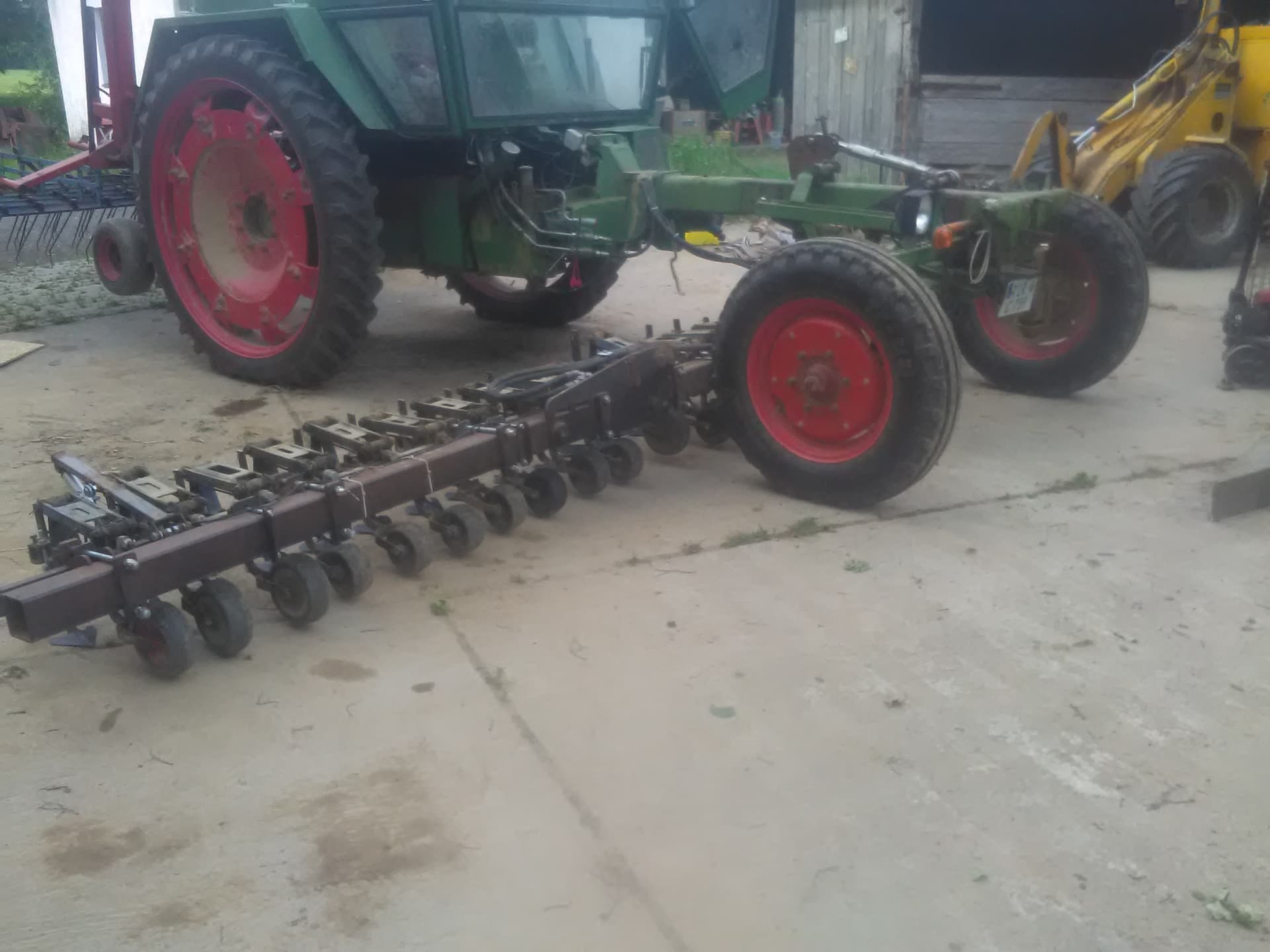
But as long as my over 40 year old Fendt GT carriers are working, I’m fine to hoe with manual steering - if only seeding is previously done with as litttle track alignment errors as possible.

I think it boils downt to the decision whether I 'll go with wide rows on ridges, or stay with my current 22cm flat seed system. I’ts a bit of circular argument, because I think I’ll need RTK precision for ridges in side hills (but may be not widht correction)

On a 60 cm wide row system, I think the allowable error is much higher than at 22 cm flat seed, I’d get a new machine attached at 3-point links, and presumably I’d start testing with a 3m seeder. So in that case I’d drop (or at least postpone) the idea of sidehill widht compensation.

When I keep my current machine, 6 m widht, trailed Horsch about 6 m long, …

… in that case, tool steering would be quite on top of my wish list.

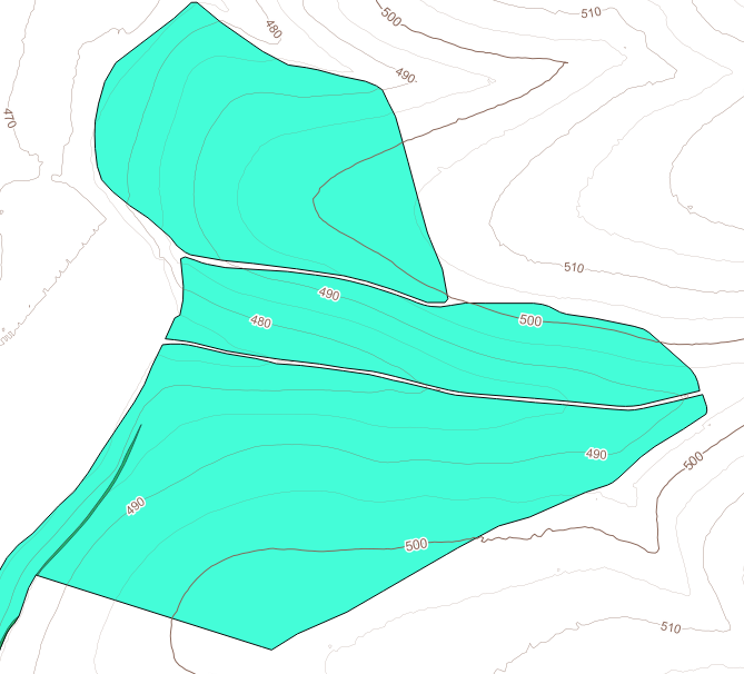
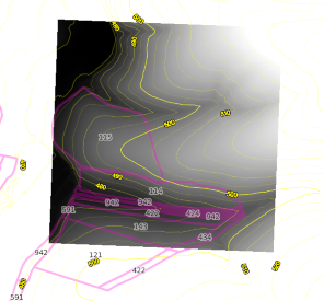
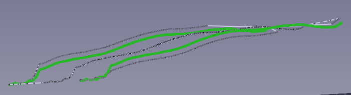
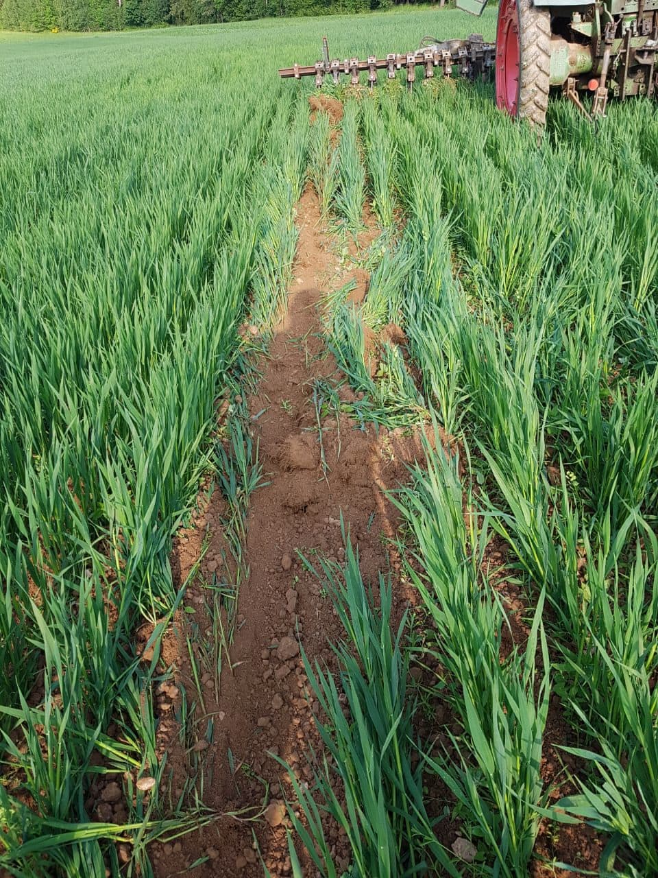
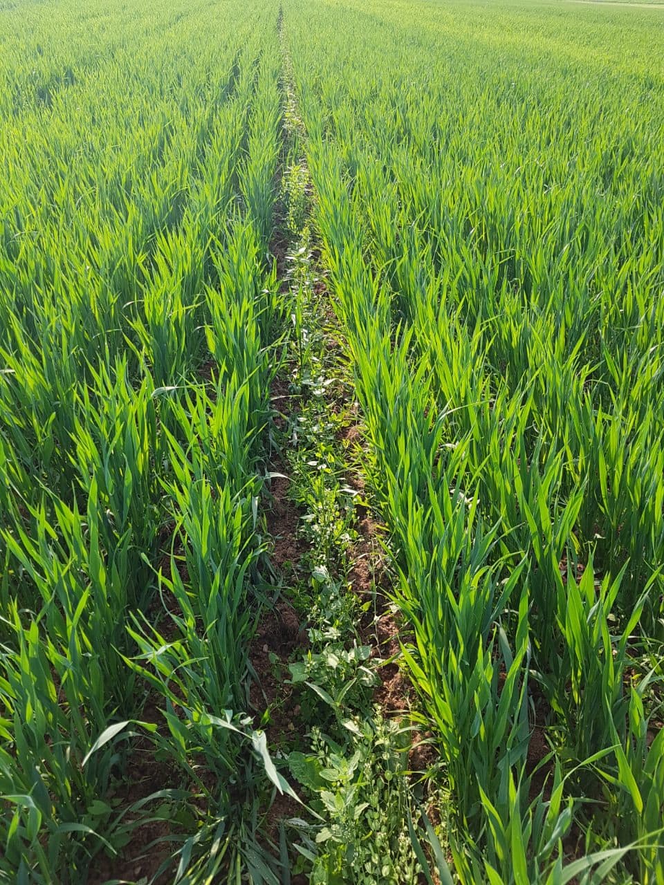
The sh… images above result form manual steering at seeding where the seeder makes unexpected shifts. It’s only a rough approximation which assumes that tool drift ist proportional to side slope. If it where thus, differential error, to a great extent, would compensate itself. But in reality, there are different soil conditions, minor tracks from previous operations etc.

Hardware for U282 with dual antennae is a nowbrainer nowadays (if it works - have just found it in a parcel half an hour ago), so no reason not have one on the tractor and one on the seeder. Boards are made by JCLPCB in batches of 5 anyway - so skd of in surplus.

For software of tool control, there were discussions along a dev version of AOG. Thus I expected do dive into the rabbit hole. Really would be great to safe that time for the weldable hard hardware.

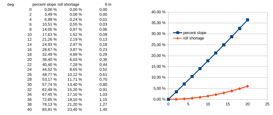
Well it’s a as simple as a simple cos.

But an old wisdom in IT says that the core algorithm takes 5 % of the effort and 95 % of the budget. User interface takes the other 95 % of the work and the other 95 % of the budget. :dizzy_face:

I know. Don’t need RTK to learn this.

At this argument I think the reason for premapping is culminating.
Another reason for premapping is my idea of “nearly contour farming” with ridged systems, to ease erosion. This imho calls for a GIS-CAD GUI, where all the extra math is built in, but the user can focus on tracks as straight as possible, fit to field boundaries where possible, avoiding long wedges at the headland, avoiding water sacks, … and the math is doing it’s job in the backgound.

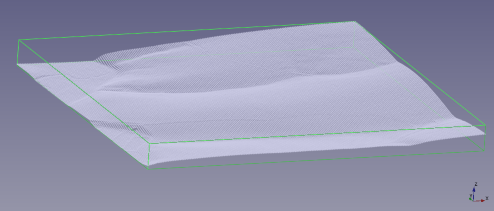
I started explorating FreeCAD over there
https://forum.freecad.org/viewtopic.php?t=97479&start=10
since it has a quite open interface to python, and since I’ve already implemented a FreeCAD workbench, enxtending it’s capabilities.

FreeCAD has a rich inventory of CAD tools, such as 2D-Offest lines, import of DEM and shape with field boundaries, B-splines for 2-times-differntial pathes (i.e. low speed on the steering wheel), interactive sketching, powerful solver for sketches for 2D-constraints, …

May be another Platform would be QGis, where all the GIS stuff is readily availble, but I haven’t even tried their CAD nor their python interface.
And I still don’t get rid of the feeling that I’m going to reinvent the wheel…

So:
Is there any tool for premapping tracks lingering around already?