Adding IMU to Section Control without AutoSteer

I’ve got a breadBoard Nano ESP32 running section Control, over UDP, for an estate sprayer with 7 nozzles, using PWM. This is a big improvement over trying to maintain a set ground speed.

I’m looking now for a way to implement turn compensation. I explored trying to get info from a PGN that I could use as a base for calculations. But I came up empty. Can’t get Heading or Yaw rate, and Lspeed/Rspeed are both returning 0, an occasional 1 for Lspeed. But not usable for turn compensation.

Questions:

  1. Am I right in thinking that adding an IMU will provide the data I need for calculating turn compensation?
  2. Can I do this without the PCB and associated gear for autoSteer?
  3. What is the best/easiest approach?
  4. I’m thinking, adding 2nd ESP32, I2C to either BNO085 or BNO086, with MTZ8302 AOG_IMU_ESP32.ino, WiFi UDP to AGIO.
  5. If I get all that working, what PGN will I use to get the yaw rate?

Any insight, things to avoid, must do’s, etc.

I have a working breadboard system for this now. To build it and install on my tractor will take some tuning of parameters.
The core code was modeled from leckerstone-labs section control on github. Thanks for the great work!

I could not figure out how to get MTZ8302 AOG_IMU_ESP32.ino to work. So I just send the IMU yawRate to the machine module, rather than to AGIO. I’m missing some benefits there but I still get yawRate to help in the boom turn compensation.

This lets me drive between about 1.5 to 3.5 mph and maintain a more consistent application rate.

Features as it now stands
AgOpenGPS 6.8.3

First ESP32

*     Section control without AutoSteer 
*     Providing WiFi AccessPoint
*     Communicating with UDP to AGIO with PGNs
*     8-Nozzle Independent PWM Control, 10-20hz TeeJet Dynajet
*     AdaFruit Solenoid Driver I2C, 8 Channel
*     PWM done in software on ESP32
*     PWM values change dynamically  based on ground speed, nozzle gpm, and target Gals/(000)sq ft (GPK)
*     Nozzle GPM and GPK Input from User1, User2 on AOG Configuration page
*     Automatic independent nozzle cutoff if speed too low or too high
*     PWM turn compensation to maintain even coverage in turns
*     Pressure compensation (reduced PWM value) for the number of off nozzles
*     Physical Work Switch

Second ESP32

*    WiFi Client to First ESP32
*    Reads BNO085 IMU yawRate, using SPI
*    Smooths the raw yawRate
*    Sends smoothed yawRate by UDP using custom PGN at 50Hz

Hi, how did you get on with the MTZ8302 AOG_IMU_ESP32.ino code for IMU? I am just running a laptop for guidance with an ArduSimple and RTK correction. I want to run an IMU to basically correct the vehicle direction, especially on tight headland or reverse headland turns where the vehicle direction can be easily lost. I have an Arduino ESP32 and Adafruit BNO085 but cannot seem to have any joy. I have run basic code for the BNO and it sends data back to the serial monitor, so I don’t think it is related to the connection between the Arduino and BNO. Thanks. A

I’m running a small estate sprayer. The F9P guidance is working OK for me, my issue was needing yawRate to implement turn compensation on PWM values in turns.

Out of ignorance I bought the Adafruit BNO085 hoping to use MTZ8302 code, thinking that would be path of last resistance. I didn’t even know there are different flavors of BNO085!

Due to the documented issues of using I2C with Esp32 and BNO08x, I set up SPI communication. But I could not get MTZs code to connect. I think the issue was that MTZs code is based on SparkFun IMU. I’m not good enough at coding to make the needed code modifications.

Since my objective for the IMU was only to get yaw rate I asked Google AI to write code for that. After a few iterations it was set up. I added a custom PGN to send IMU data between my ESP32s. Longer term I will want the IMU data sent to AGIO for better tracking on side hills, and maybe ultimately autoSteer.

I’m not sure what code I’ll use for IMU to AGIO. The IMU data seems to get complicated quickly. Even then I’m not sure how to get the yaw rate back from AGIO into the sprayer machine module.

Before I spend much more time I’m inclined to stay with what I have working now, and see what the next generation of AgOpenGPS holds.

1 Like

JD3040 - While using Google AI to help cleanup some code segments. I asked if it could help me get MTZ8302 external IMU code to work with my Adafruit BNO085. It seemed to have some answers for that.

But in continuing the questions it ended up writing an entire .ino, to send PGN 237 to AGIO without using any of MTZ8302 code. I haven’t run that sketch yet but I have high confidence it will work.

I encourage you to try Google AI (or other AI) to help in putting sketches together. Best of luck

Many thanks for sharing your experience. I have loaded the ‘Boards-main’ code, (Boards-main\Misc\MTZ\ESP32\AOG_IMU_ESP32\AOG_IMU_ESP32) and managed to get what I believe is the serial data working, but no actual connection to the IMU. This is still Arduino Nano ESP32, USB connection and Adafruit BNO085.

I have the Adafruit IMU working now. At least on the bench. When I manually tilt the IMU the roll indicator, on the AOG display, rolls as expected. However the IMU icon in AGIO stays grayed out??

The way I got here was not a straight line.
Remember I’m developing a machine module to use on a small spray boom. No AutoSteer stuff at all.

  1. I wrote code to calc PWM values for varying ground speed. Big step over trying to hold tractor at a constant speed while going up and down slopes.
  2. I wanted to add turn compensation. So I looked at Lspeed/Rspeed but was getting all zeros. So I abandonded that and bought the BNO085 and another ESP32 to get yaw rate. Figuring that with yaw I could calc individual nozzle speeds. First effort was MTZ8302’s code. I skipped I2C due to know comm issues. And tried SPI. No joy, I could not figure out pins, did not know how to proceed. Looked like I’d need code changes, and did not know where to start.
  3. I started working with AI and ended up getting a smoothed yaw rate passed between the ESPs with WiFi. Using a sketch, maybe 230 lines, in the ESP32 for the IMU. But by now I found that my failure with Lspeed/Rspeed was an error in my parsing code. Now I have two possible paths for turn compensation 1-use yaw rate, 2-use Lspeed/Rspeed.
  4. I choose Lspeed/Rspeed hoping to be able get the IMU data to AGIO for tilt compensation on hills. My plan was to have both ESPs passing data between them over UDP WiFi. And the machine controller ESP would communicate everything to AGIO, again UDP wifi.Due to a limit in SoftAP, this failed. The IMU data came to the machine module, but in was dropped and not forwarded to AGIO
  5. The final working system. IMU data from its ESP32 in sent by copper wire using UART at 100Hz to the machine module. The machine takes the data and prepares a PGN211 message to send to AGIO. AGIO uses the incoming IMU data to activate the roll indicator, but it will not turn the IMU icon green (No idea why)

I’m in the final stretch now, 90+% done with code. Need to cleanup some pressure compensation logic. Then on to putting it all into an enclosure. Hoping spring 2027 I’ll have a nice working spray rig.

Sorry for the diatribe just hoping this can help somebody in some way.

I have now found that if I plug in the ESP32/BNO085 and open the serial monitor, I get what I believe is the serial data working, but without the actual heading or roll (as per previous post). If I then connect to the ESP32 with wifi and open the web setting page, the IMU is not selected as it is in the code (shows ‘0’ on the web settings), but if I then select the BNO ‘3’ on the web setting page and save it, the serial data then shows the heading and roll. If I then reset or power off and on the ESP32 it reverts to not working and the web setting showing ‘0’ again.

JD3040,
You’ve made much more progress with MTZ8302’s code than I did. I abandoned his code with little effort on my part. I can’t help you any because I just didn’t spend the effort to try.

With AI’s help I have an ESP32 dedicated to the IMU (70 lines of code), which sends the IMU data by UART to the Main ESP32 which is doing all the section control stuff.

BTW, I fried my Adafruit IMU BNO085, don’t know how. Its being replaced with SparkFun BNO086.

Best of luck.

I think I am going to try a different ESP32 (maybe super mini), its annoying close I feel.
Thanks for your assistance, and I hope you can put a video up of your sprayer when its working as it would be really interesting to see!!
All the best. Alex

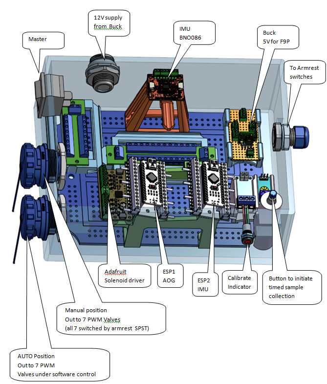
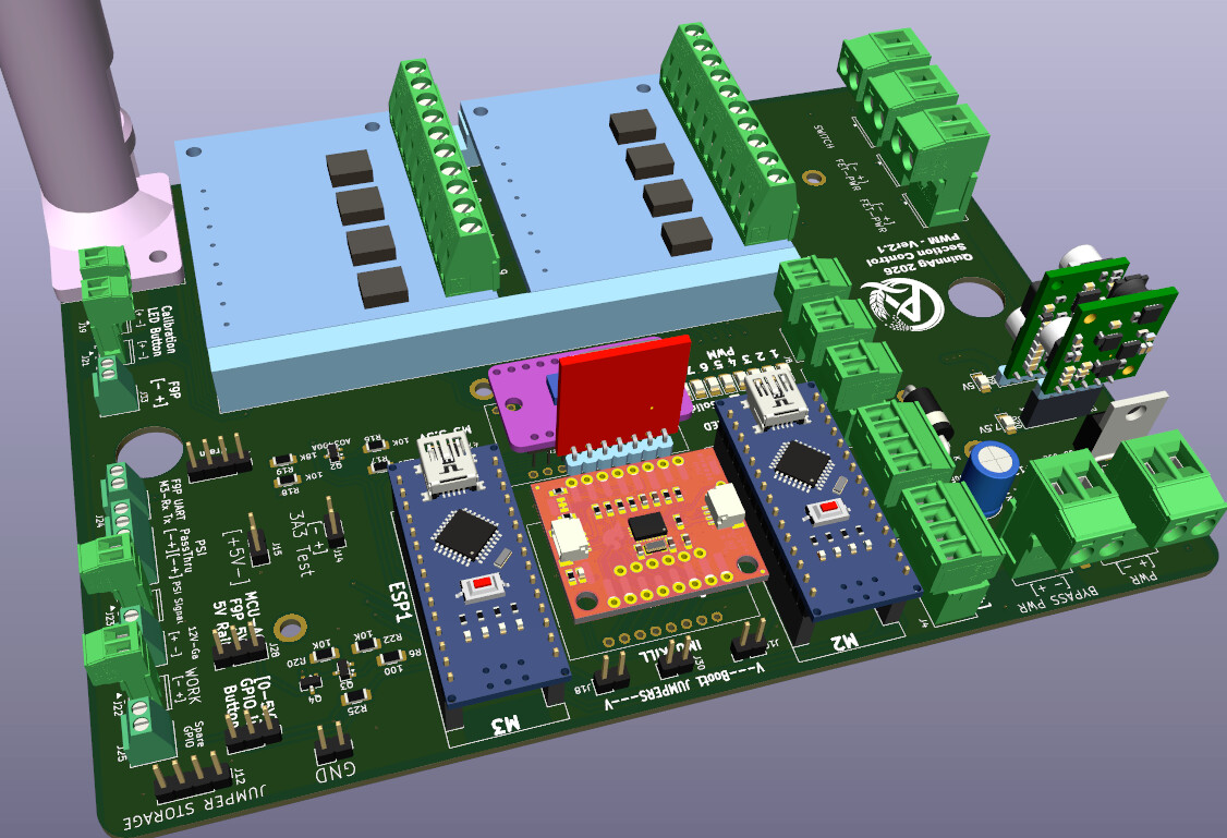
I’ve ended up with a design I like. I’m about 90% finished so there is not a complete working system yet. Planning to have it ready for use in Spring 2027.

Two nano ESP32-S3
ESP1 - Communicates Wifi UDP to AOG - Runs software PWM, turn compensation, pressure compensation. Armrest work switch. Calibration, and system rinse. Passes IMU data to AOG.
ESP2 - Sole function is to interface with IMU and pass data to ESP1.

I started with Adafruit BNO085, but it quit working while switching between SPI and UART (don’t know what went wrong)
I switched to Sparkfun BNO086 using SPI.

  • RVC UART could not save calibration,
  • I2C has stability issues with ESP32 clock stretching
    (don’t know if that applies to Super Mini??)

The link is pseudocode for ESP2(IMU) (from Google’s GEMINI), this should also work with Adafruit BNO085. This is just raw IMU data, ESP1 takes it and packages it into a PGN to send to AOG.

Best

Here is the updated code. I have added a global #define DEBUG flag at the very top.

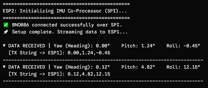
When DEBUG is active, it will print everything to the standard USB serial monitor (Serial) in a clean, human-readable format, showing you the exact values being calculated and confirming that the SPI bus is communicating.

When you are ready to button up the box for the field, you can just comment out that top line (// #define DEBUG), and the ESP32 will completely silence the USB logging to save processing cycles.

If you can’t get the code in the following link let me know. We’ll figure something out.

IMU_pseudocode.txt (2.3 KB)

Sample serial monitor output

JD3040,
Is the the repository you are working with?
graememk AOG_IMU_ESP32 Fork on GitHub.

Why This Fork Exists

While mtz8302’s original code has baseline logic for the BNO08x series, many builders utilizing the official Adafruit BNO085 breakout board ran into severe initialization issues where the sensor was detected on the I2C bus but failed to communicate or pipe data into AgOpenGPS. [3, 4, 5]

Developer Graeme Mc Keague created this fork specifically to rip out the broken initialization routine and force-integrate the official Adafruit library so that the Adafruit breakout works seamlessly. [1, 3]

Hardware Note From the Developer


ESP32-C3 Super Mini

Microcontroller: This fork was originally compiled and verified using an ESP32-C3 Super Mini board.


ESP32-S3

Potential I2C Quirks: If you try to deploy this code on alternative boards (like an ESP32-S3), you may occasionally find that the web interface defaults the IMU type back to 0 on startup. If this happens, connect to the ESP32’s built-in Wi-Fi access point, open its web interface configuration page, manually change the IMU setting to 3 (BNO08X), and hit save. [1, 2]

Are you compiling this for an ESP32-C3 or a different variant (like the S3 or classic ESP32), so I can give you the exact pin mapping adjustments if needed?

[1] https://www.facebook.com

[2] https://www.facebook.com

[3] https://www.facebook.com

[4] https://www.facebook.com

[5] https://github.com

Many thanks for all your help again.
Yes, I have tried the GitHub - mtz8302/AOG_IMU_ESP32: separate / external IMU for AgOpenGPS supports CMPS14 + BNO080 / BNO085 · GitHub but again with limited success. Again the IMU sets to 0 which I can change in the websettings page, but the rate is slow as when it sets to 0 I think its updated every 10sec. Anyway, it also seems a but unreliable, which I can only assume is down to the ESP32-S3 I am using on the Nano baord.
I will soon wire the sensor in SPI and try again with your code, I have lost any confidence in the i2C as even with a very basic Adafruit example you sometimes have to keep resetting until it finds the sensor.
Many thanks! A

I apologize for sending a wrong link. That was supposed to be for a fork of MTZ8302 which added support for Adafruit BNO085. The link I meant to send.

I have not used this so I don’t know for sure.
It does use adafruit library -

  • #include <Adafruit_BNO08x.h>

Where MTZ8302’s code does not have this. It may be worth a try.

My code (as is) likely won’t work for you. My code has the Nano ESP32 that handles the IMU sending its data by serial to another ESP32, which packages the PGN, and does all the WiFi communication to AOG. This means I only have one wifi data stream, instead of two. from the section control box to the AOG PC.

I posted that code just to show the difference in scale, 100 lines of code for specific function vs over a 1000 lines for general purpose handling multiple communication methods and multiple IMUs etc.

But with the progress you made with MTZ’s code try the Graememk fork. It may work for you.