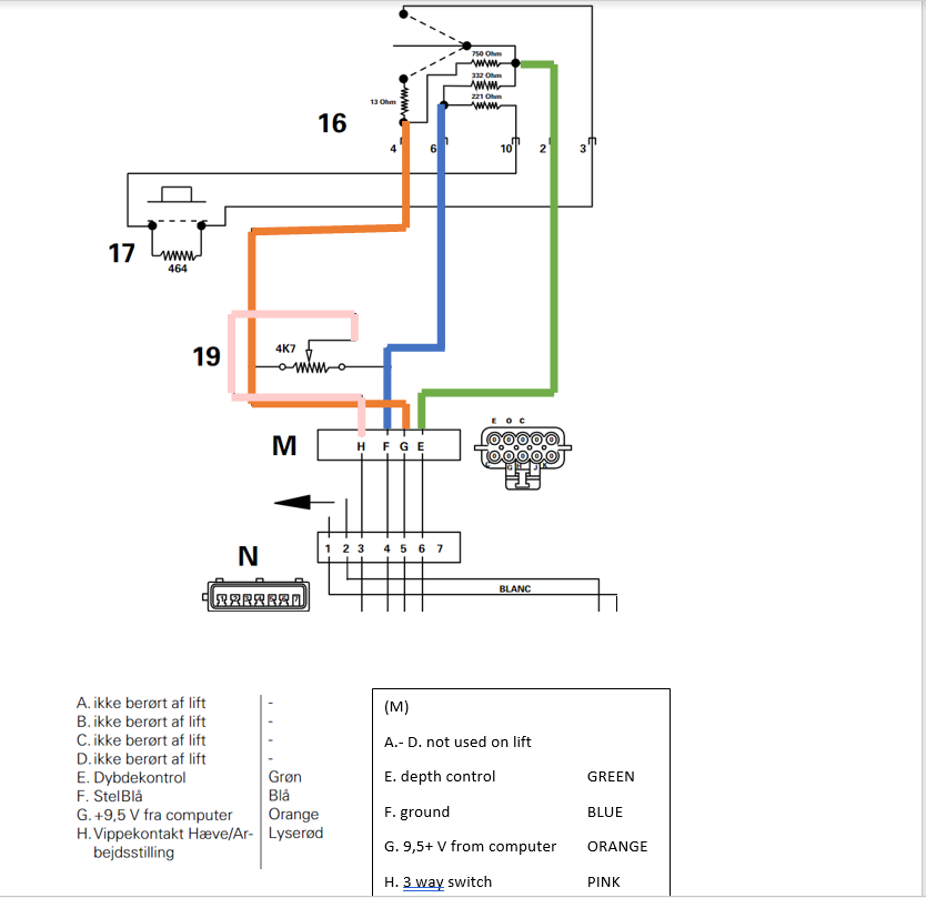
could it be that on switch 16 the 4 , 10 , 2 ,3 correspond to the 4 legs of the switch?
2 feels like ground
2 - 4 → 350 ohm
2 -10 → 330+220 → 550ohm (which goes to the quick lower that has another 460 ohm? )
How about we add 13ohm resistor between 2 - 6 and see if it lifts instead of lower?
That is really helpful, but again shows it’s more complicated than I thought and it would need to be if they didn’t want to sell these for +50€ prices. What happens at the 19 potentiometer? Does it affect the ohms of the circuits or could its measurement determine whether its going down or up? Is there signal coming through there from ELC bypassing the switch? Should I put the relay between 19 and 16 or M and N or does it matter at all?
Not quite sure but my guess is that 19 can regulate the voltage and then the computer has parameters to what position the lift would need to be according to the computer
hope this makes more sense, not sure if you can just put in a relay with the ressistors there since the power takes the easy way it would still be 9,5 V that goes back instead of the lowered voltage
Thank you, this explains some of the measurement I got. However my switch has different pinout numbers and it behaves strangely if there is only resistors in there? It has some resistance between all of the pins but when powered it has only momentary resistance like of there is a relay disconnecting all of the pins. However there is voltage differences between all the pins. I will put my measurements below and continue measuring.
Now when I think about it. It seems like the voltage goin back on wire E or 5/2 would be the determining factor of the height anyway. So I will try if just pulling the connector of will do the trick or do I still need that 4,9/5V going through.
I’m assuming the computer will need the voltage from the depth control in order to function… Might throw a fault code if it doesn’t get a voltage that’s in between the parameters
But through all these resistors, etc we’re basically doing a very overcomplicated “voltage divider”.
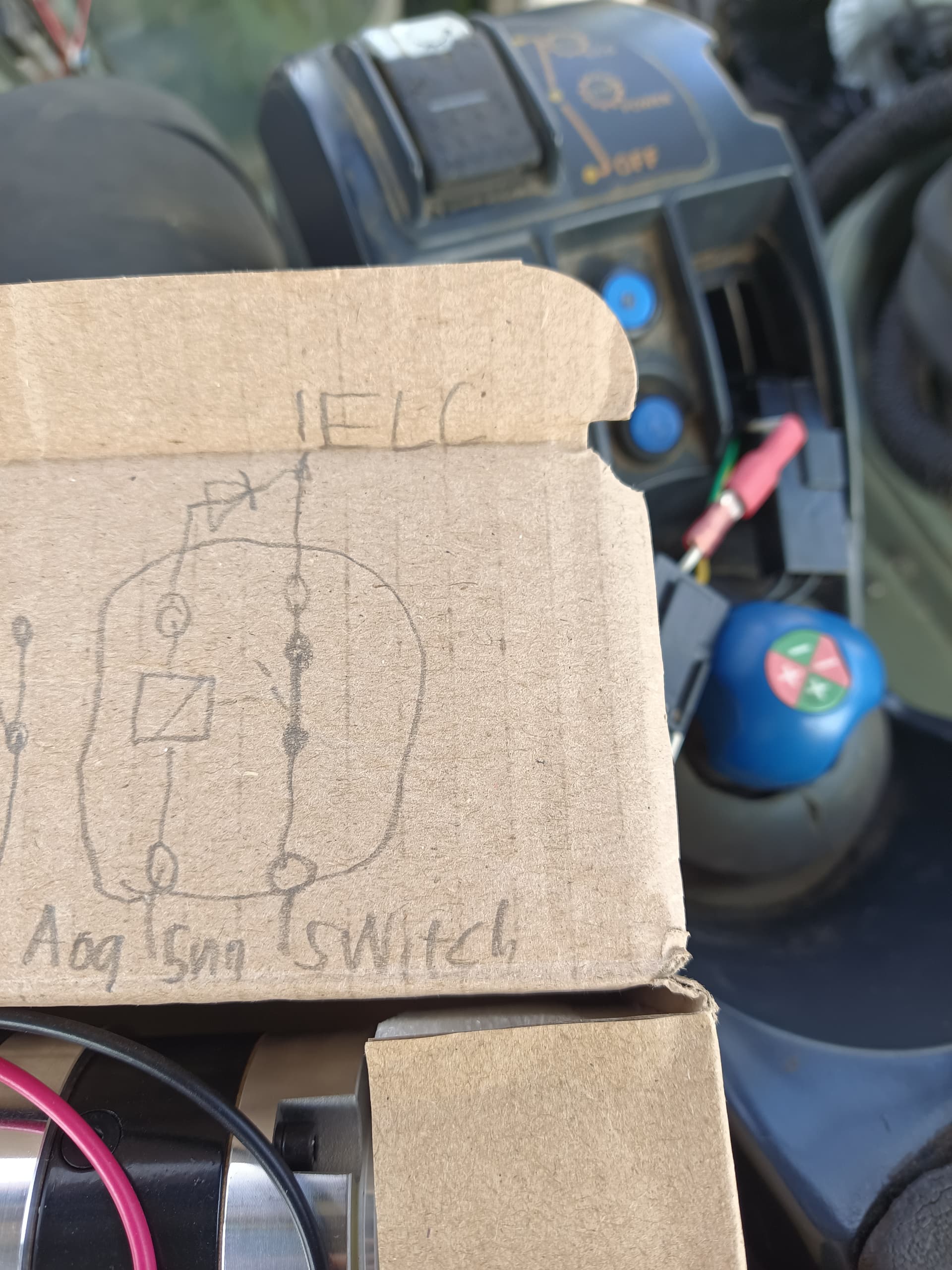
With that being said one of the guys in Hungary ( @Joci ) “simply” used 3 voltage regulator to create 3.3 , 5.5 , 6.6 volts (that was his lower / neutral / raise ) and using a DPDT switch he puts control to his contraption and let the relays switch the right voltage. Maybe he’ll share pictures.
I wonder if there could potentially be a DAC output on the AIO board added in the future for stuff like this. Maybe something like a digital potentiometer or DAC with op amp to get a configurable 0-12v output.
It indeed throws the error code 1-9 when the wire is cut. Now I guess it needs a relay cutting of the 7,24 input when aog tells it to lift and a way to input 5V simultaneously. Could that 5 V be sourced from AIO board trough ampseal or even use the same wire for continuous 5V and power suply using a diode to prevent 7,5V backfeed?
I googled it and learned about voltage dividers. Do I need to make a divider with two resistors and a wire to gnd or is just one resistor in wire enough? What resistor would I need to get 5V out of 7,24 or 9,5 volts?
//These are the pins available on the AIO boards AMPSEAL: #define HYDRAULIC_LIFT_OR_UP 26 //A12 was: Hyd_up Used to lift up the hydraulics #define HYDRAULIC_LOWER_OR_DOWN 27//A13 was: Hyd_down Used to lower the hydraulics #define HYDRAULIC_TRAMLINE 38 //A14
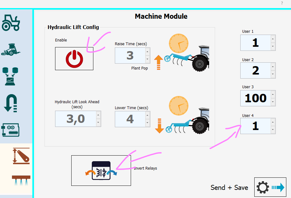
You want to play with the User4 parameter in AgOpenGPS:
uint8_t user4 = 0; //0 - disabled , 1 - Pulls the relay and keeps it that way , 2 - pulls and release it after N second
We had to invert the relays to get it working with relay board.
Here:
We got lucky with all of our tractors. (Athough we rarely used this feature.)
Long story short AOG is not capable to “lower” the hydraulics. It can only “raise”. So when its lifted it’ll stay lifted no matter what the software tries.
This was achieved by “cutting” the cable that was powered by the switch when lowered. And the ECU automatically raised the hydraulics up. So our relay is wired as C + NC and when activated it disconnects that wire.
However all the tractors are different, so not sure what’ll work best for you.