I’m from Europe and on this side of the pond we often use the rear hydraulics a lot. Controlling that would be essential. Fortunately we have 3 pins that are unused on the Ampseal 23 connector. We could totally triggers those like @bricbric did on the older boards.
So lets see what we have:
A0
A6
A7
A12 *
A13 *
A14 *
A15
A16
SDA0
SCL0
(* is on the ampseal)
We have 2 kind of hydraulics in the tractors of ours (please help me extend):
1 trigger line that crosses wires (i.e. you tell the position: up / down / float ) by default up or down is having constant 12V. So when it’s down we could cross the 2 wires to make it go up, or the other way, simple DPDT rely.
2 trigger line: this has: (lower , neutral, lift) this I’d leave it in neutral position then we can trigger with AoG to put it down / lift it up for X seconds. (the kind of switch depends sometimes it’s 12 / 0 / 12 sometimes it’s 3.3 / 5 / 6.6 )
So this leaves us with 1 or 2 pins available on the Ampseal23. These could be section control or tramline control. But then tramline might need 1-2 pins depends…
The following will require us carefully planning the chip: (I2C address might conflict with the IMU)
I’ve received some suggestions to use the SDA / SCL with: Arduino | Adafruit MCP23017 I2C GPIO Expander | Adafruit Learning System
BNO085 default address is: 0x4A can be changed to 0x4B
MCP23016 default address is: 0x20 can be incremented until 0x27 (so 8 expansions each having 16 inputs our outputs, in theory even the planter monitoring could be solved)
CMPS14 is on 0xC0
This means we’d have unlimited output pins on a “machine” board (hydraulic lift and sections via expansions)
And would still have 3 on ampseal and another 5 hidden on the AIO board. + via expansion a lot more.
(Maybe 1 more ampseal? )
I started do write some code but currently focusing of “stealing” the info that is sent to AutoSteer to control the hydraulics.
And this AIO board I think should show up as Machine Board in AgIO which is beyond my current knowledge.
And after this I guess we can also think about the CAN buses…
Does it worth to go down this rabbit hole?
Anyone who would like to team up?
Probably won’t be a problem MCP23017 has a very flexible I2C address set by 3 jumpers(10 options) so you probably can run both on the same bus without any interference.
Such shift register on an expansion board we could also attach for the ampseal connectors 3 free pin…
Then we’d could build a small board.
I propose:
3 pins to control hydraulics
1 pin for keeping it up,
2 pins for the lifting action, lowering action with timings
4-5 pin that would signal for tramline
left / right
If we make it into a machine board then:
6-16 11 pins for the section control / custom
There’s an ampseal 14 connector for which we could put everything and box it neatly. That would give us a standard connector for hydraulic button control (I think) + tramlines + 8 sections. And it would be different shape so hard to mix it up with the other ampseal 23. + would leave the possibility for a V3 board with 2 ampseal connectors.
aye I yet again updated my post so seems we have 2 totally valid option to move on with this.
1 could be an inside the box expansion option with inputs and outputs
Other would be an outside of the main box with outputs only but could be connected to the current ampseal 23 connector.
This really got me thinking about auxiliary controls for AOG. I am starting to think that maybe a whole other auxiliary control unit might be ideal. Say for example you removed the linkage cables from your hydraulic remotes and placed a servo on each valve to actuate it(and a second if you have flow control), and a potentiometer on each control lever with a switch to indicate the neutral position.
This way you could have full computer control that is seamlessly integrated but also have a system in place to allow a manual override. You could have this all driven from a dedicated unit to control and monitor your hydraulics along with any other onboard systems(pto for example). That would basically follow the lever positions. My reasoning for this is that this way it can also act as a standalone unit that can function even when the rest of the autosteer system is off.(maybe even utilize interrupts to wake up the unit for when the tractor is off)
Not really sure how useful it would be very practical, but I think it could make for a very clean install while still remaining functional.
The part I want to do a proof of concept will look like hits:
I2C could be used as input and output → has no external header → I’ll not touch it.
the 3 external pins I’ll connect a shift register (as it takes 3 pins + 5V/GND ) in theory we can have as many of this as we want in series. But this can only be an output. But still to control valves, relays it’s fine. So most of our machines will need just 1 of this. Planter needs an extra one (as ours has 4 sections + 1 tramline) , sprayer needs also an extra one.
but this way we don’t need any extra Arduinos as the Teensy could do everything. (Maybe have 2 threads started 1 for autosteer 10-50Hz and 1 for machine board with like 5Hz speed )
That would work. Why is the I2C pins on the amp seal not an option?
The only reason I suggested a separate microcontroller for machine control was for situations in which you would create a complete electronic control of your remotes. Then you would need a lot more than just a shift register to control it. And the main reason is so you can have it on standby 100% of the time, even when the key is off, to make it truly transparent. But simple outputs are what you need most of the time anyways.
You don’t have the I2C pins available on the current ampseal connector. But I2C might actually allow you to have the Teensy + Arduino manage the same I/O expander.
I was mistaken. Makes sense now. Another suggestion I have would be to run software I2C on the ampseal pins. Wouldn’t really take much more than running shift registers and is actually very easy to implement.
We ended up redoing the integration but this is what we ran in the tractors for now: GitHub - gunicsba/AgOpenGPS_Boards at hydliftv2
It was tested in 4 tractors so far and works fine everywhere.
Is there a wiring diagram of some sort that I could follow to get the lift function working on our mf6265? I saw
The diagram in the link above had MF there, but I didn’t quite understand it and I am not sure if mine has type 1 or type 2 switch. And how and where I should copy the code?
My brother was wiring the tractors and have no picture of any of the 3… Basically he went with this logic:
Lower the implement then find a way to trick the 3 wires so we can lift it up.
When switch in cab is in UP poistion (i.e. implement is lifted) it should not matter what AgOpenGPS is doing and regardless of the relay state it should stay up.
Connect the wires with a relay.
Then we add a voltage regulator for the relay board to have 5V.
And pull the trigger to ground via the AIO pins.
Is aog sending a continuous signal when lifting? and from which pin I should get the signal in ampseal? I haven’t looked at the switch yet but I guess either one relay switcing from down position to up wire and back could do the job if it is the type that stays in up position while getting signal and when signal is cut switches back to down. If aog or teensy is not sending continuous signal I guess I need a relay that keeps whichever position the signal leaves it at and then another switch that I can choose between aog and manual control. I will look at the switch soon and maybe make a simple scetch drawing of the wiring.
Use a relay board from aliexpress the 2 pins shoud operate in 2 modes:
User4 = 1 → when lifted we’ll lift and keep it up until lowered then use the other pin to keep it down.
User4 = 2 → lift for N sec, then turn off, lower for N sec then turn off.
(User4 is a parameter on the hydraulic config screen of AgOpenGPS)
Invert relay can be used to invert the relay state. (by default we pull it high as it is activated by connecting it to ground)
Work switch off disables it.
//These are the pins available on the AIO boards AMPSEAL: #define HYDRAULIC_LIFT_OR_UP 26 //A12 was: Hyd_up Used to lift up the hydraulics #define HYDRAULIC_LOWER_OR_DOWN 27//A13 was: Hyd_down Used to lower the hydraulics #define HYDRAULIC_TRAMLINE 38 //A14
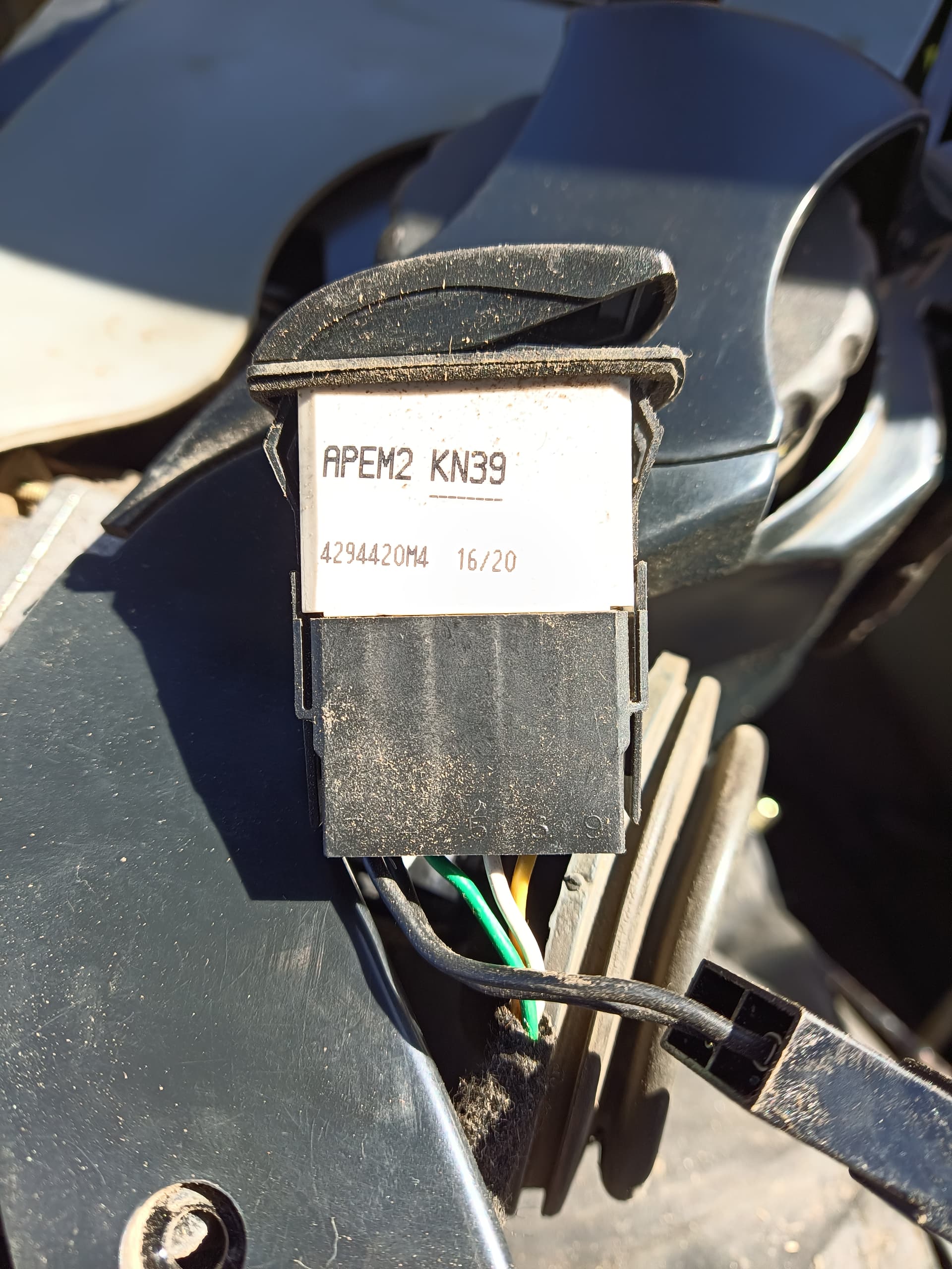
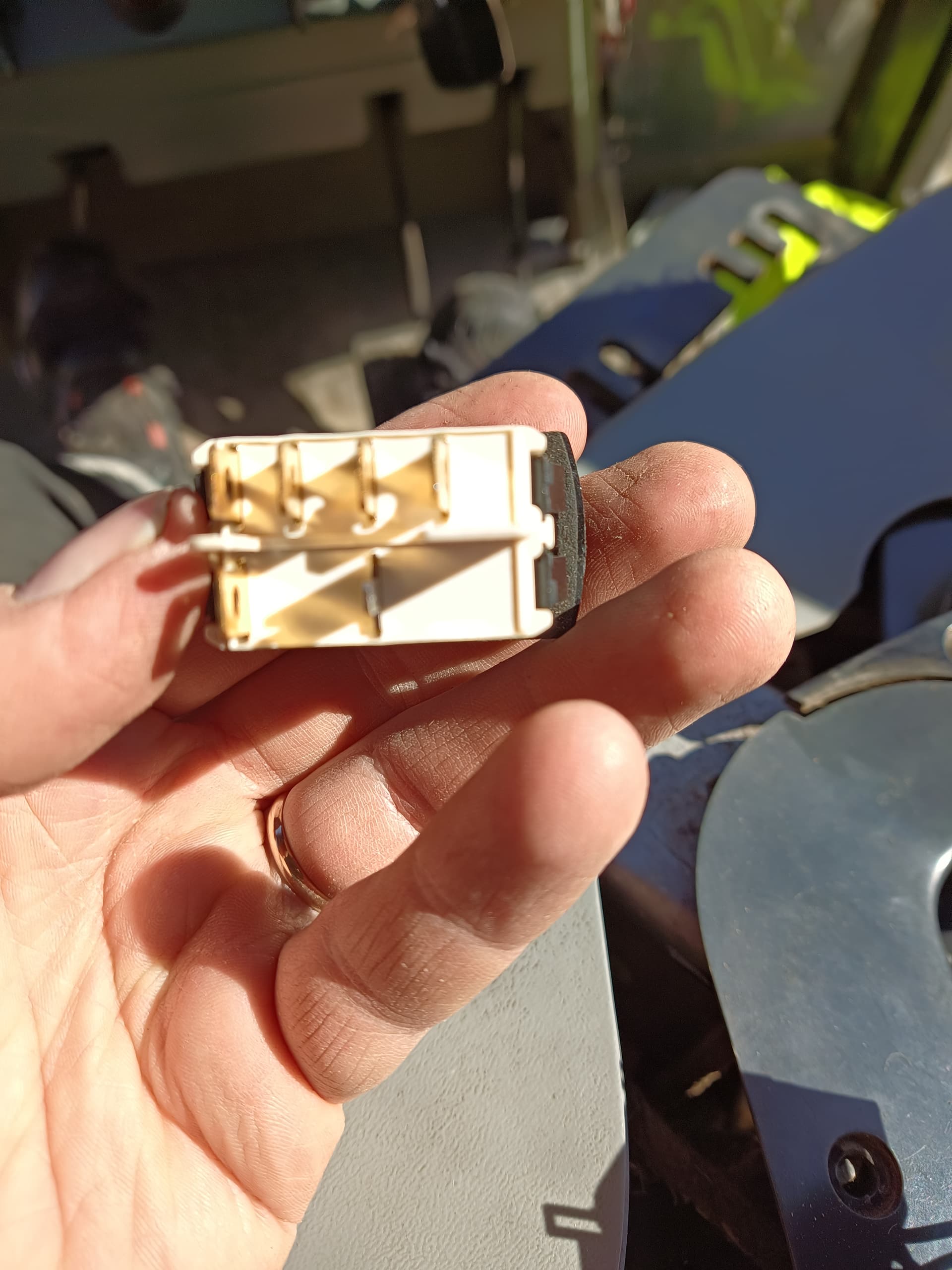
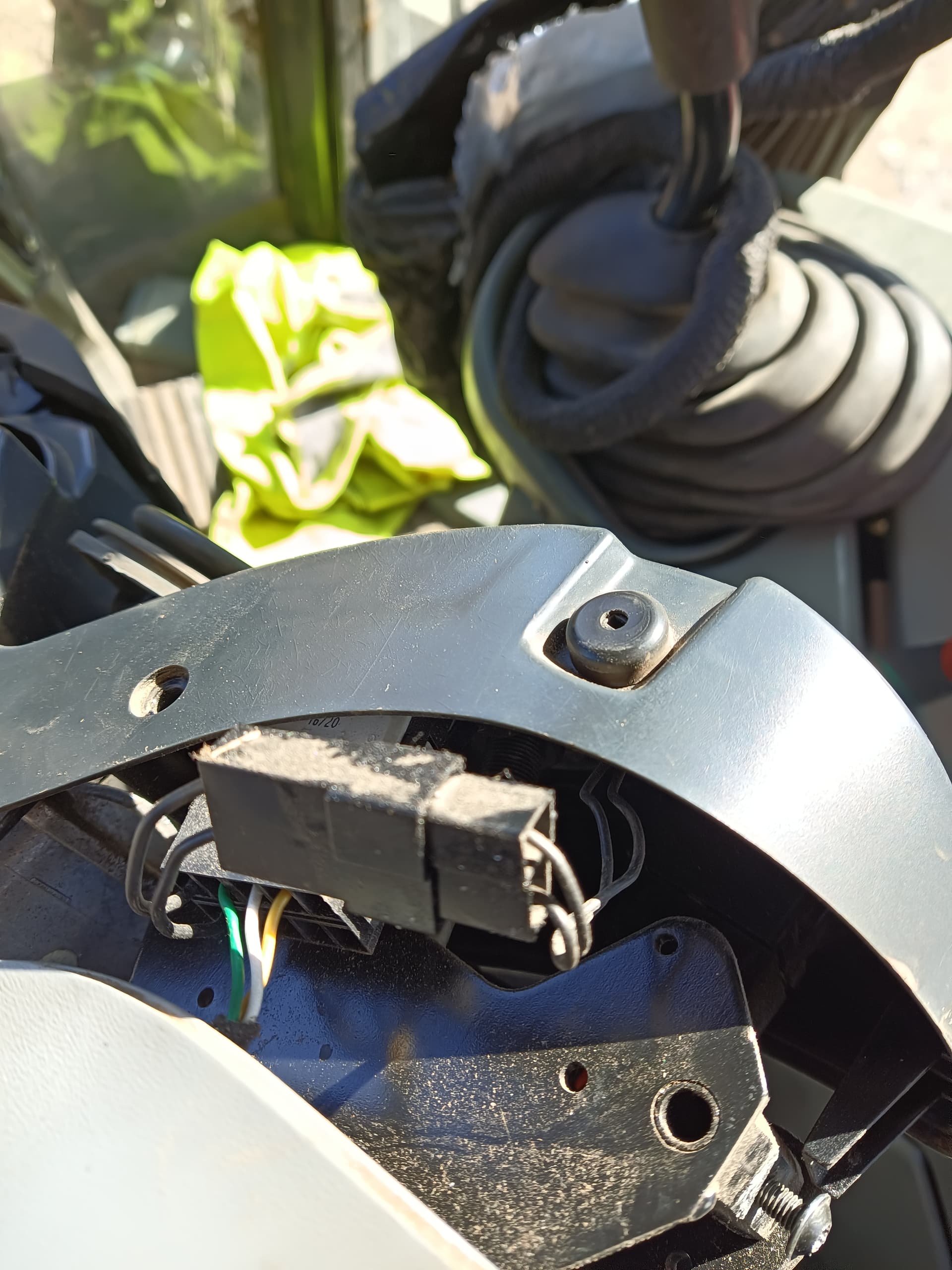
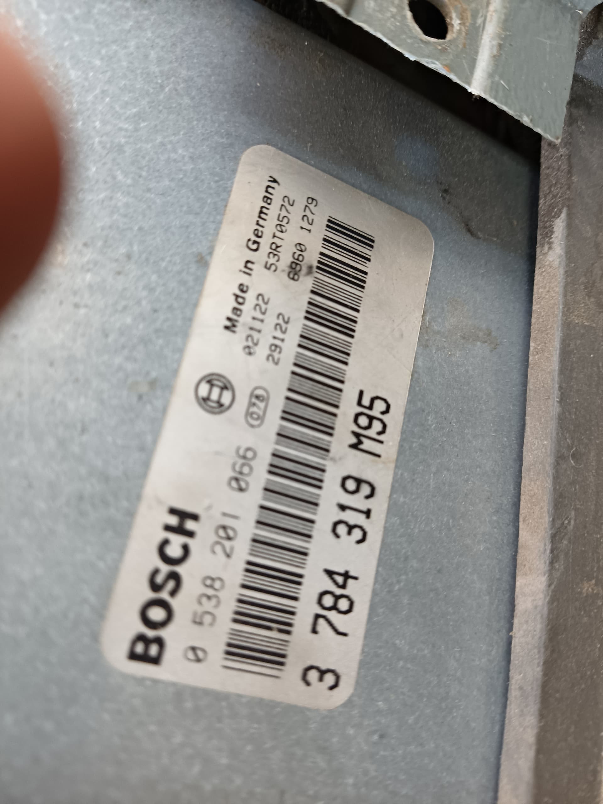
Well it wasn’t as simple switch as I expected and there seems to be ELC unit behind. Is it likely to result in error in ELC if I put relays in the wirings?
This small black side button is interesting, it lowers the linkage fast when pushed and releases it back up when released, it would probably be the simplest one to use as it has only two wires going in it.
My brother says that if you have your switch on lowered position but you “cut” the wire it automatically raises it. So his way of wiring is simply having the relay to cut the lowering wire which tricks the computer to lift the rear up.
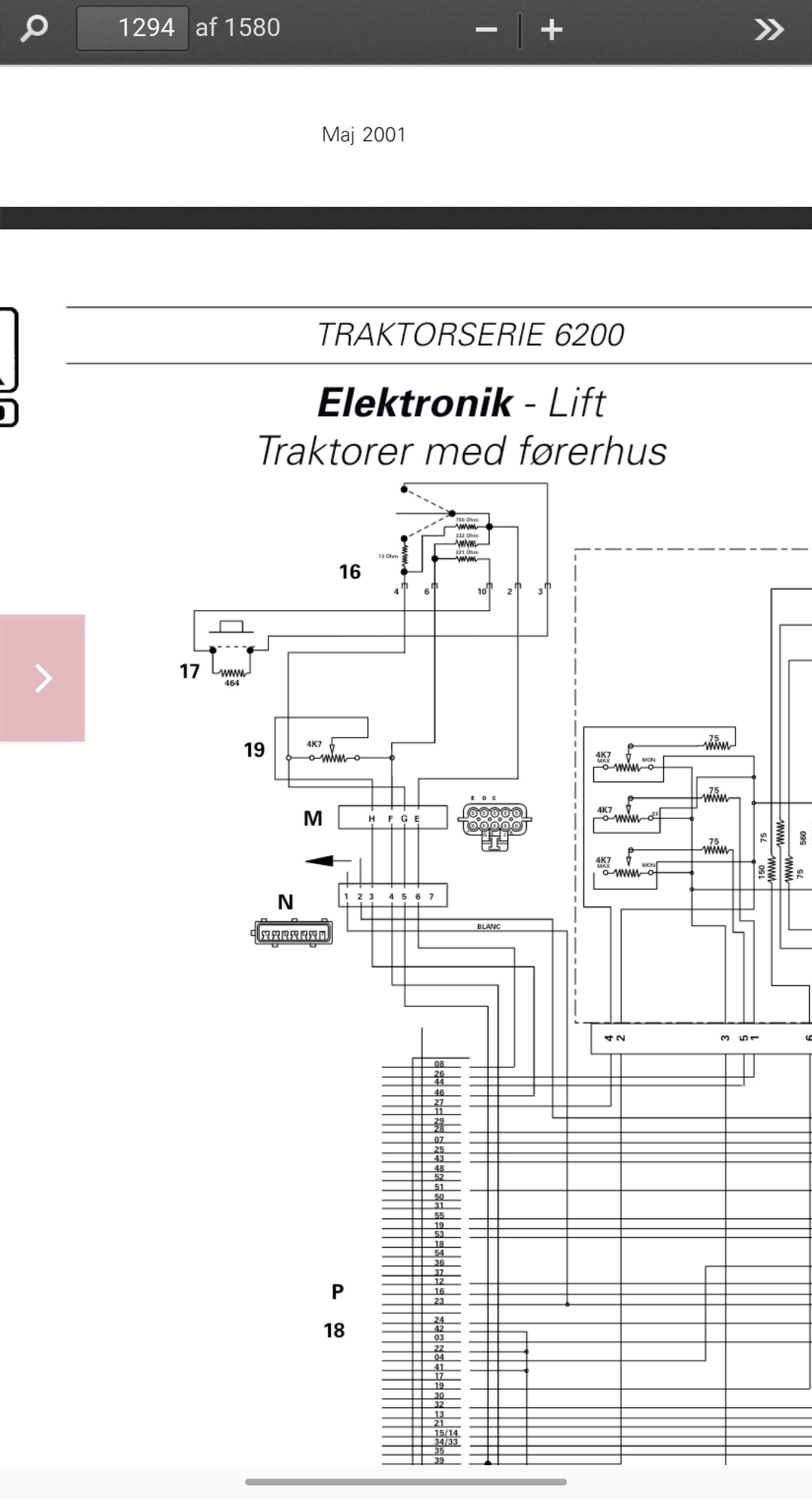
Don’t know if this helps any but this is the wiring diagram for the switch no. 16 no. 17 is the “quick lowering” for ploughing and no. 19 is potentiometer for depth control. The F and G in the plug (M) are for raising and lowering