Your currently powering the board with a usb cable, what happens when you supply it with 12v via the ampseal plug without the usb?
Have you added that ads1115 module yourself, i don’t think you need that
They are a nightmare to try and get. Think mouser have some but the postage kills it
From what I understand from the telegram group, it was built with a blue led (diyfarmtech) so according to that it should be right. Next step is to check serial ports when I put it on the tractor
It is a dutch site but they sell male and female.
Right. Flashed the teensy and it worked, IMU was sending data. Turned it all off and come back today and it no longer works, like before. What the hell is happening
If you reflashed the teensy and it all worked fine and now it doesn’t maybe you got a bad teensy thats not holding the firmware.
Have you inspected all the soldier joints on the teensy and the pcb and underneath, might need a magnifying glass. Also try probing the pins with teensy connected from the teensy to the board to make sure they are all in contact
This is a long shot but I know when my brother was putting his board together he did not get the pins of his ampseal connecter crimped correctly and it would short out randomly. This caused him a lot of frustration but if your board is consistently powered and the Teensy keeps losing programming this would not be of any help. Can you explain a little more what is not working.
It’s a weird one, because the next day I came to use it and the IMU was reading perfectly! And the time after that! Without changing anything. So I don’t know exactly what was up with it 
Hello everyone. I just completed my first order for the AIO V4.5 boards with JLCPCB and received an email asking me to confirm component placement. Before I click yes I would like to confirm with those that have done this before that it is correct.
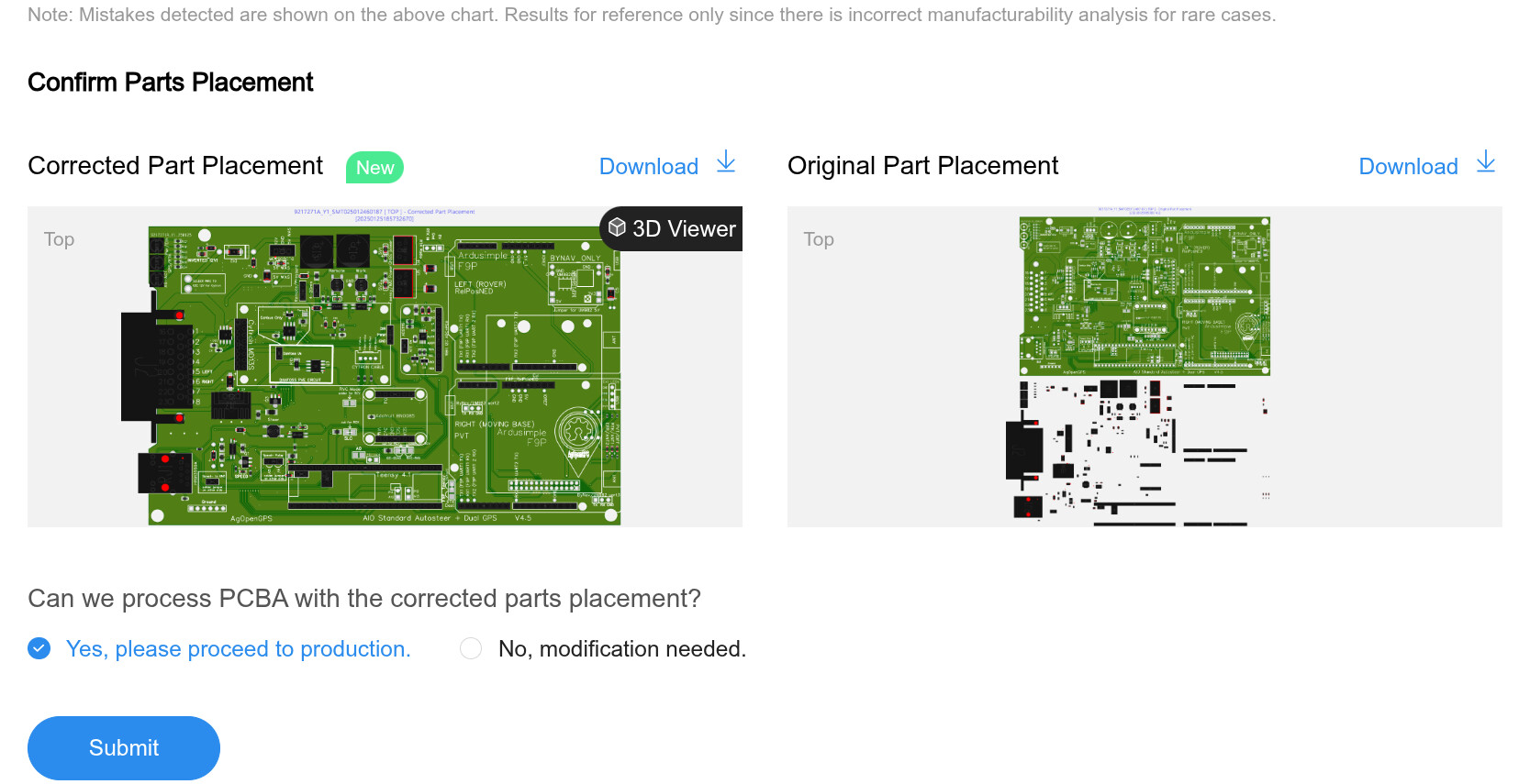
Hello everyone,
I am currently assembling the v4.5 board and planning to have JLCPCB solder the components. However, I ran into an issue while ordering because three components are not available in their inventory. I am looking for suitable alternatives that JLCPCB can source and assemble:
- AMPSEAL23-776087-1 (C378893)
- GNSSpower PWRM-TH_K7805M-1000R3
- MC7805CTG TO-220-3_L10.0-W4.5-P2.54-T
I also checked the Excel file with alternative components, but I couldn’t find replacements for these parts.
If anyone has experience with alternative parts that work well on the v4.5 board and are available for assembly through JLCPCB, I would really appreciate your recommendations. Ideally, I’d like components that fit the existing footprint without modifying the PCB.
Thanks in advance for your help!
In another post it was mentioned that there was a problem getting the K7805M part and a suggested alternative was here. I didn’t even realized I missed it until afterwards so I ordered it and put it on myself. I am not sure if that is an available alternative part on the website.
I am not much help with the other parts but I would imagine that the amp seal could order and place yourself. Or just wait a few days or a week to see if stuff comes in stock. I actually waited a little while before I made my own order because certain things were out.
okay thank you
Trying to troubleshoot my board. Everything seems to work except for controlling the Cytron. I am initially setting this up on the bench yet for my first run and that seems it shouldn’t be an issue from the videos that I have watched. I am using the phidgets motor. I do get a power light on the cytron and if I use the buttons on the top of the Cytron it will spin the motor left and right. If I go in to the autosteer configuration menu it does seem my WAS and values change when I move it. If I hit the tractor icon so it goes green it doesn’t work no mater how much I move the WAS. The one thing that I did notice is that the PWM value never changes in that menu when green and I think it has something to do with that. Only thing is I can think of is if going through the autosteer wizard is required to turn something on. Or maybe there is something wrong with my Teensy since that seems to control the PWM. Thoughts?
If not moving aog prohibit output.
Open autosteer setting AND expand that window, check button/switch settings. Make tractor at bottom left green and watch the pwm number under that icon. They only rice if AOG allow.
I got it now. I didn’t have the button hooked up for the previous test. I didn’t think at the moment it was needed to test it. Thanks!
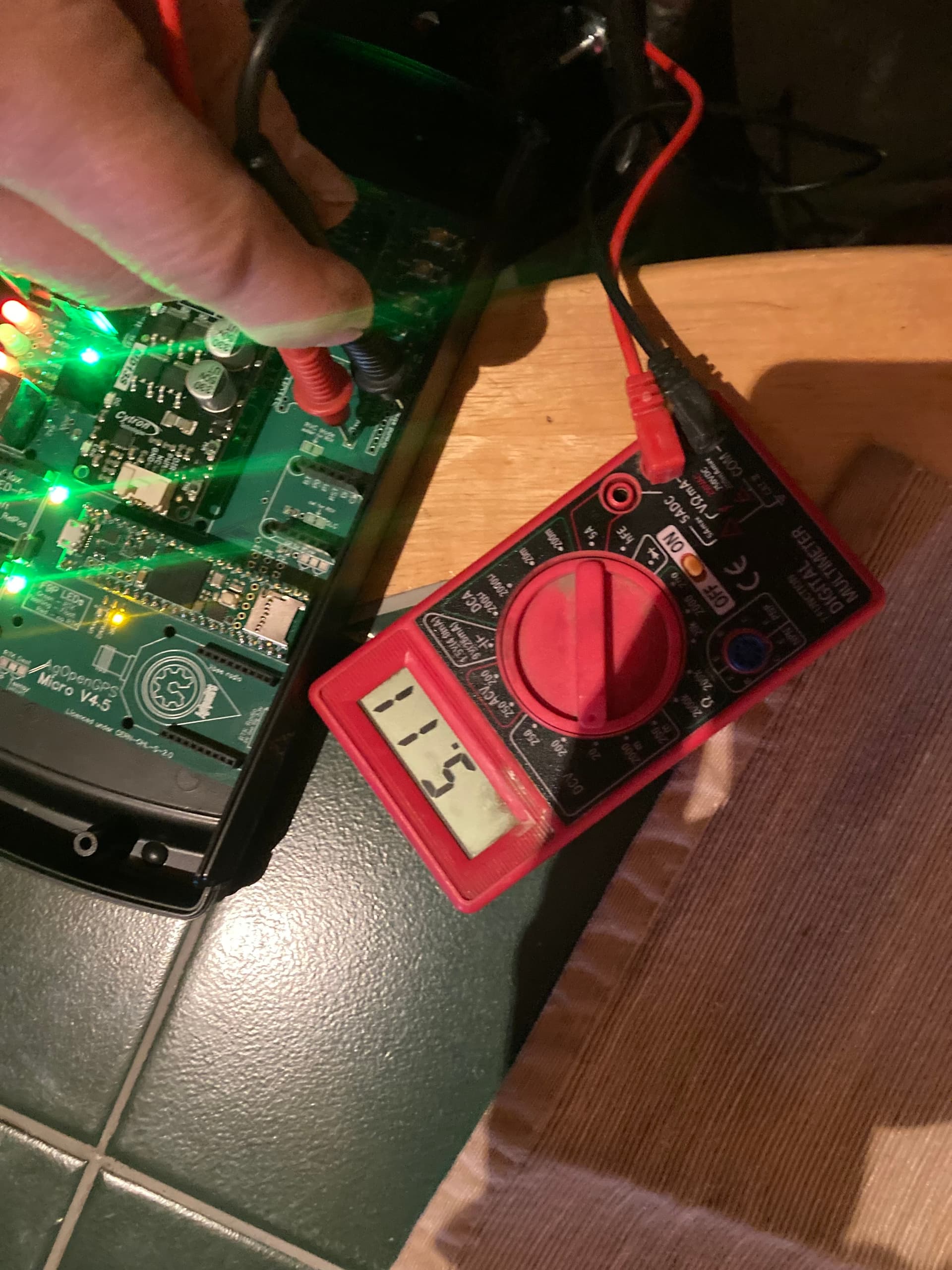
I bought a 4.5 micro PBC. I am not getting 3.3v at any of the test points. Any suggestions on what I need to do to fix this? Thanks in advance.
[/grid]
I can’t see from your picture but do you have the regulators installed on the board?
There is a good chance that is what I messed up. My background is data science so I am more out of my depth than I expected. When I ordered the board there wee a couple parts that were not available because of sanctions so I ordered the closest thing I can find. Here is a picture of my board. I can only add one attachment. I will add my "bill of materials in pdf in the next response.
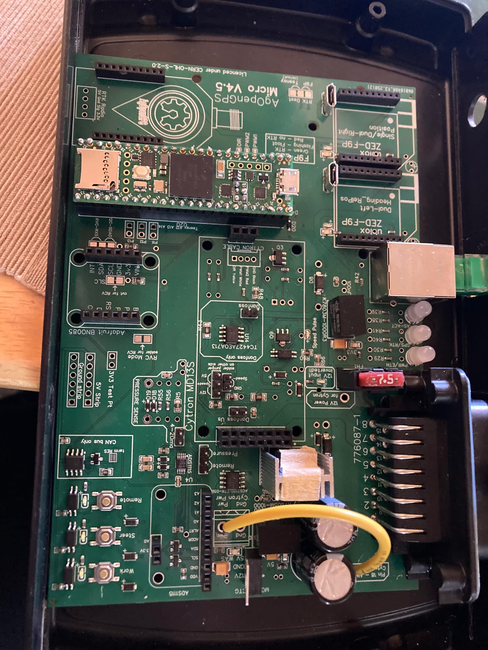
Here is my bill of materials. As a new user I couldn’t upload so I had to paste this in. Thanks again for helping me sort my mistakes.
| Column 1 | Column 2 | Column 3 | Column 4 |
|---|---|---|---|
| Comment | Designator | Footprint | JLCPCB Part # |
| 270Ω | R1,R3,R16 | R0603 | C22966 |
| 6.2kΩ | R56 | R0603COPY-NOSILK | C4260 |
| 1kΩ | R43 | R1206 | C4410 |
| 100nF_CAN | C16,C3,C19,C26,C11 | C0603 | C14663 |
| MCP2562-E/SN | U17 | SOIC-8_L5.0-W4.0-P1.27-LS6.0-BL | C53609 |
| VUSB | H20 | HDR-TH_2P-P2.54-V-F | C7499322 |
| PESD1CAN,215 | D5 | SOT-23_L2.9-W1.3-P1.90-LS2.4-BR | C75176 |
| 12kΩ | R55 | R0603COPY-NOSILK | C22790 |
| 5VWAS | LED4,LED3,LED5,LED8,LED7 | LED0805-R-RD | C2297 |
| 2N7002 | Q4,Q5 | SOT-23-3_L2.9-W1.3-P1.90-LS2.4-BR | C8545 |
| Remote | LED_STEER,LED_WORK,LED_REMOTE | LED0603-R-RD_WHITE | C2290 |
| HR913550A | RJ1 | RJ45-TH_HR913550A | C163507 |
| SS54_C22452 | D6,D8 | SMA_L4.4-W2.8-LS5.4-R-RD | C22452 |
| ADS1115IDGSR | U4 | MSOP-10_L3.0-W3.0-P0.50-LS5.0-BL | C37593 |
| 10nF | C7,C23 | C0805 | C1710 |
| DY-339URUYGW/SN | AS-ACT,GPS/RTK,PWR/ETH | LED-TH_3P-BD5.0-P2.54 | C459134 |
| 1000uF | C15,C17 | CAP-TH_BD13.0-P5.00-D1.2-FD | C88743 |
| D882_C9634 | Q3,Q9 | SOT-89-3_L4.5-W2.5-P1.50-LS4.2-BR | C9634 |
| 100uF | C8,C9,C10 | CASE-B_3528 | C16133 |
| 1N5819WS | D20,D41,D19,D18,D16,D17 | SOD-323_L1.8-W1.3-LS2.5-RD | C191023 |
| EL3H7(B)(TA)-G | REMOTEOPTO,STEEROPTO,WORKOPTO,SPEEDPULSEOPTO | SOP-4_L4.4-W2.8-P1.27-LS7.0-TL | C32565 |
| MC7805CTG | U6 | TO-220-3_L10.0-W4.5-P2.54-T | C22456 |
| HEADER_Cytron2x8 | J1 | HDR-TH_16P-P2.54-V-F-R2-C8-S2.54-1 | C30734 |
| MICRO180°JB | USB3,USB2 | MINI-USB-SMD_U255-051N-4BH70-XS | C456007 |
| HEADER_6PINS | H13,H14 | HDR-TH_6P-P2.54-V-F | C2897369 |
| K7803M-1000R3 | U5,U3 | PWRM-TH_K78XXM-1000R3 | C909661 |
| 10kΩ | R47 | R1206 | C17902 |
| TC4427AEOA713 | U14 | SOIC-8_L4.9-W3.9-P1.27-LS6.0-BL | C20551 |
| 4-20ma | H21,H19,H22,H4 | HDR-TH_2P-P2.54-V-M-1 | C2905434 |
| HEADER_3PINS | H8 | HDR-TH_3P-P2.54-V-F | C146243 |
| SM4007PL | D4,D7,D9,D11,D13,D14 | SOD-123F_L2.8-W1.8-LS3.7-RD | C64898 |
| H_TEENSY | U29,U30 | HDR-TH_24P-P2.54-V-F | C2883741 |
| 1nF | C20 | C0603 | C1588 |
| 120Ω | R60,R64 | R0805 | C17437 |
| A2005HWV-2X3P | CN2 | HDR-TH_6P-P2.00-V-F-R2-C3-S2.00 | C2906071 |
| 1510.521 | U13 | SINK-TH_L15.0-W10.5-H21.0 | C4649 |
| 22850102ANG1SYA02 | H18 | HDR-TH_2P-P2.54-V-F | C429966 |
| 0603_RED | LED15,LED16,LED17 | LED0603-RD | C2286 |
| 1.5kΩ | R73,R74 | R0603 | C22843 |
| AMPSEAL23-776087-1 | J2 | 7760871-EXT | C378893 |
| 2kΩ | R23 | R0603COPY-NOSILK | C22975 |
| 178.6764.0001 | FH1 | 178.6764.0001 | C142933 |
| 200Ω | R66,R5,R48 | R0805 | C17540 |
| IRF5305PBF | Q8 | TO-220-3_L10.0-W4.5-P2.54-T | C2623 |
| 5.1kΩ | R22,R63,R17,R61 | R0603 | C23186 |
| DIR_LED | LED9,LED10,LED12,LED11 | LED0603-RD | C72038 |
| 2.2kΩ | R62,R71,R12,R13 | R0805 | C17520 |
| RemoteorPressureInput | J4,H5 | HDR-TH_3P-P2.54-V-M | C2937625 |
| ACS712ELCTR-05B-T | U1 | SOIC-8_L5.0-W4.0-P1.27-LS6.0-BL | C44471 |
| TS-1187A-B-A-B | REMOTE_SW,STEER_SW,WORK_SW | SW-SMD_4P-L5.1-W5.1-P3.70-LS6.5-TL-2 | C318884 |
| 1kΩ | R29,R30,R38,R39,R40,R41,R42,R19,R26,R6,R10,R18,R20,R21,R25,R27,R28,R46,R49,R50,R51,R52,R53,R54 | R0603COPY-NOSILK | C21190 |
| HEADER_2mm | H9,H10,H1,H7,H11,H12 | HDR-TH_10P-P2.00-V-F | C691436 |
| HEADER_ADS-MCP6002 | U16 | HDR-F-2.54_1X10 | C2897373 |
Sorry I didn’t look closely at your previous post. You do have 5 volts but not 3 volts? 3 volts should be supplied by the teensy. Check that it is getting power and check your solder joint on the vin and 3.3 volt pin.
Edit: zooming in on your picture it looks like the solder joint on the vin pin ( labeled 5v) might not be making a good connection. Some of those other pins look questionable as well. You want the solder to look like a little tent solidly connected to the board and not like a blob.