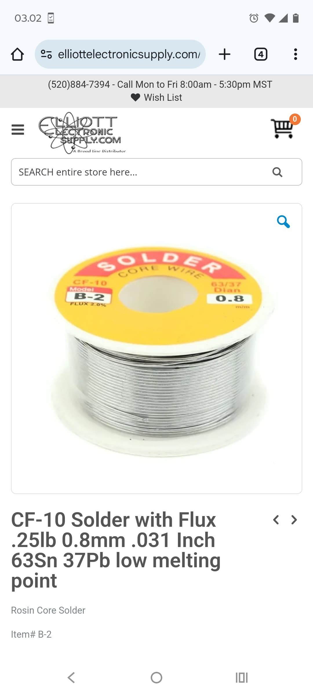
I agree with the soldering problem, but @ScottJFrisby if you use solderpaste it is easier to transfer heat to the solder ring on the teensy and solder float better.
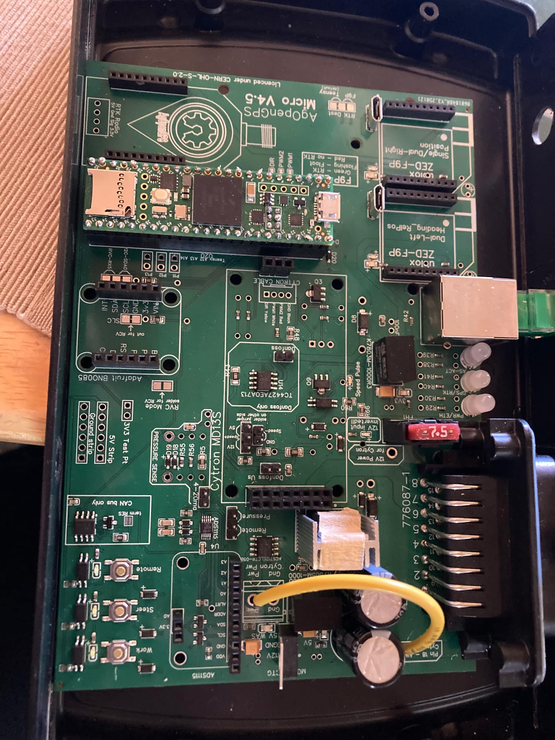
On the micro you find a 7803 voltage regulator to feed the F9P micro. Beside that regulator it has 3 v 3 printed, try to test voltage there.
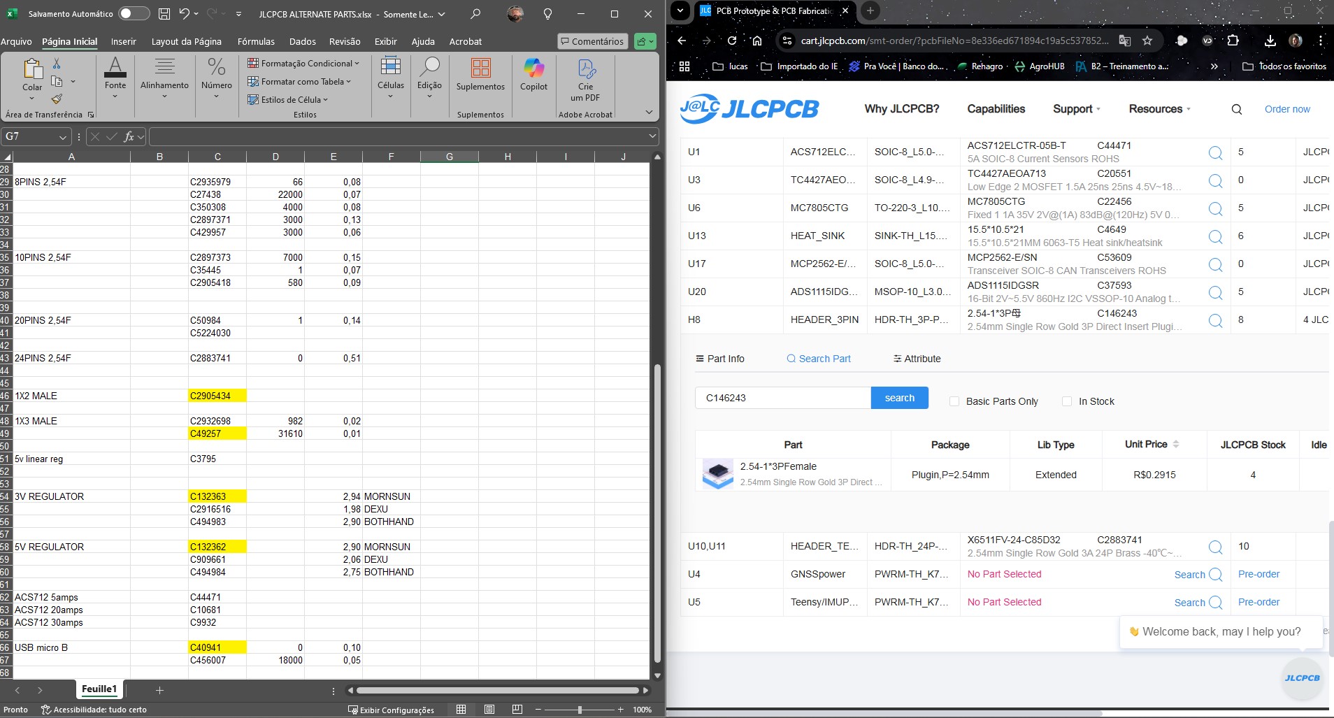
I went to order the PCB All In One, and what happened? Some components are missing, as you can see in the screenshot. But I checked the list of alternatives, and there are none. So now what? What should I do?
These are the regulators I think. Micro use some 5v and 3v, Std all 5v.
Be careful with theses, sometimes JLCPCB put them backward.
These are Trough hole components, you can easily buy them at mouser/digikey and solder them yourself.
This is because the default Mornsun regs have been “cancelled” due to Russian sanctions. JLCPCB must have erased their number.
For anyone this helps, the 6 pin header for Ethernet is Samtec MTMM-103-09-G-D-280
Digikey and others sell it and this is the part that PJRC sells via their own website. 100% correct heights when used with a v4.5 that has the female socket on the board.
but something isn’t working. When I connect the 24 volt step up to the power It seems to decay the power feed to the board - I will get 5 volt but it rapidly declines to 0 volt within a few seconds. Any thoughts on what I am doing work?
Also, the jumper wire on the Cryton to the board for the 24 volt, is that on the ground or on the positive?
Are you connecting pin 18 to cytron in power? Have you put the jumper wire on the board aswell which is dedicated for this purpose, pretty sure its marked on the pcb itself ‘pin 18 cytron in’ or something similar
I am working on finalizing my v4.5 board and have a couple questions:
If I am using the lock pin to control a relay for disconnecting the steer motor so I don’t have to modify the cytron, do I need a NO or NC relay? Or do I still need to mod the cytron?
Do I just connect the ground from the cytron to any of the ground pins in the Ampseal? Or should I run a wire out of the enclosure?
… May be a sign of a short on the regulator side? Check all voltages.
… Jumper wire is +24V (positive) and must connect to PWR (positive).
Your pcb screenshot posted recently:
… There are a lot of bad solder joint on your teensy’s header soldering!
… around PWR terminal, looks like there is a bit smoke sign ? Is the trace on the bottom side ok?
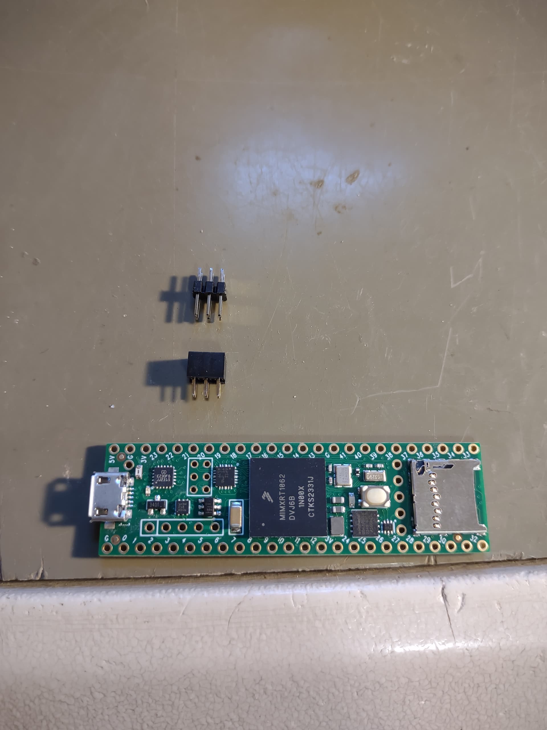
I’m just starting work on my board, soldered headers on my teensy and then moved to the little Ethernet pins. Before I soldered them on I noticed that the female headers on the Aio board are shorter and my pins on the teensy won’t reach. What does everyone do about that?
This is how I do it. Solder the female to the teensy and bridge the gap with the male. Think you could also pull pins out of regular headers and they would fit but it wouldn’t be as clean.
Has anybody been able to solve this problem?
I’ve been wanting to order PCB for more than a month now and header 3 pin is still unavailable.
Also, does anyone have spare AIO v4.5 standard board he doesn’t need?
Hello, I have a question about using the Standard AIO for my Danfoss John Deere valve.
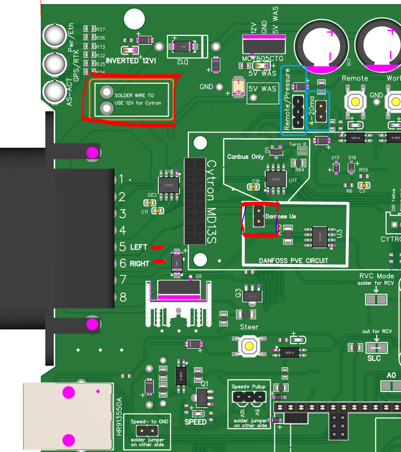
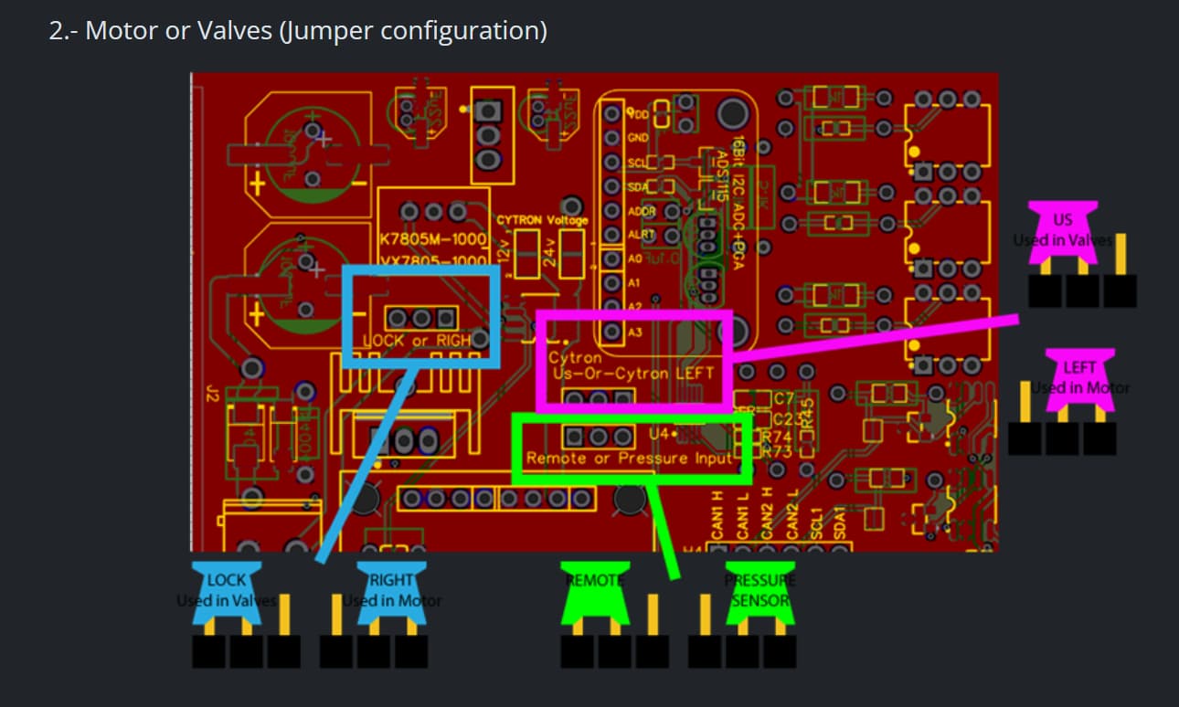
1- I need to put a jumper on the PCB for US.
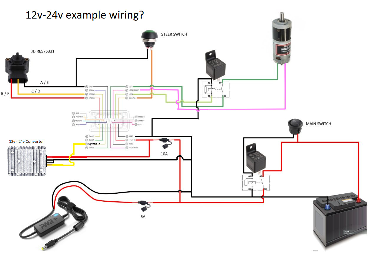
2- Connect it with a 12V cable from the Cytron