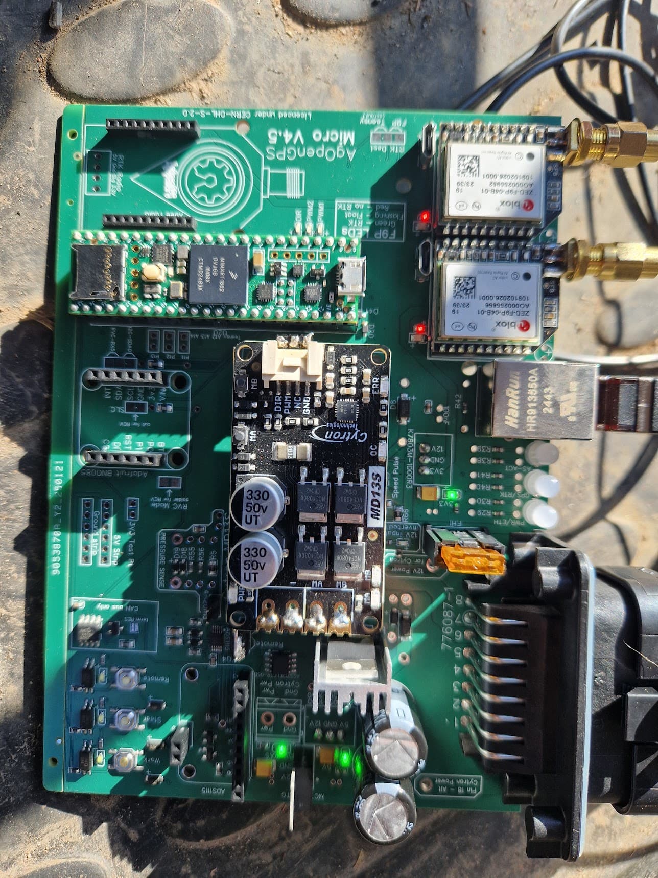
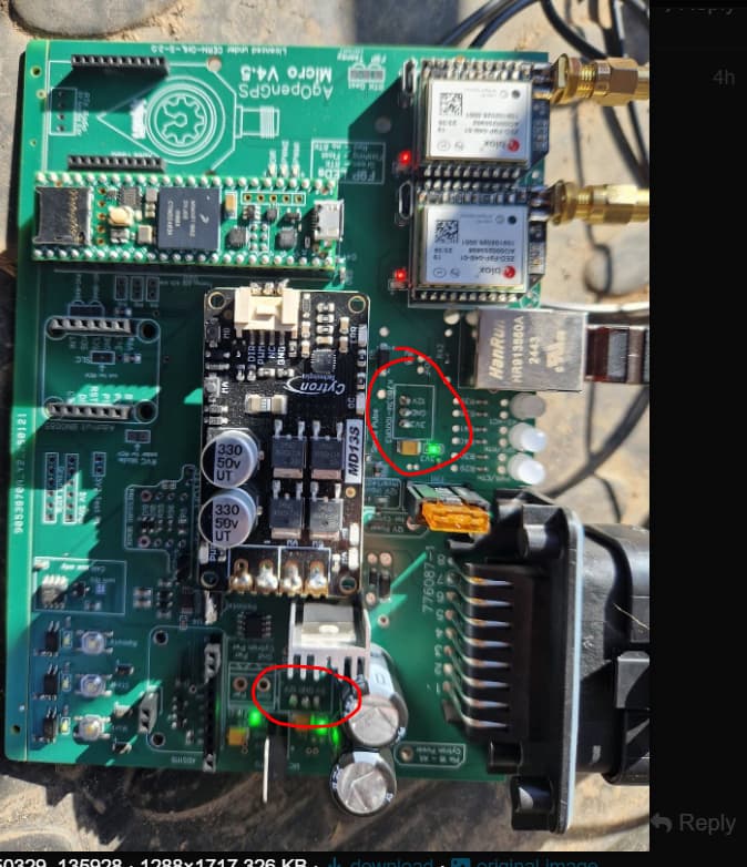
I am trying to get the v4.5 system working. Currently when I power the board up teensy lights up and I get ethernet connection, but about 30s later teensy lights go out and also these 3 led on the board.
I have measured 5VIN pin, it gets around 4,75 V in. Teensy 3,3Vout pin is 0V when teensy is disconnected from the board (as it should be).
Has anyone some ideas why teensy stops working? It takes around 45 min of waiting after which teensy lights will get on again (when powering again up). I have 2 different teensys, both act the same way
I’m not sure I understand the problem. You lose all power to the board after 30 seconds? If all the lights go out on the board that is what it is indicating. What are you powering the board with?
What’s going on here?
When you remove the Teensy and F9Ps and Cytron and add 12v power, do you measure 5v and 3.3v where you should?
Looks like they maybe soldered from the bottom. ![]()
- Why are they soldered from this side? JLCPCB did not include 5v and 3v voltage regulators. I ordered them myself from mouser, but the pinout did not match the layout on the board, so I placed them from the other side to get “clean” layout.
- I do get 3,3v and 5v where needed. 3.3v for F9Ps and on the test pins. 5v from teensy input and also from the test pins.
First issue that I had with board was voltage dropping on the teensy below 3v. I thought it was board fault, but in the end in was input 12v that dropped down due to bad connection on the relay. That sorted out I did get the board (with teensy) working for about 30 min (tried to setup AOG and read WAS values), and then suddenly I got no communication anymore, when looked at the board teensy lights were out (before orange light was flashing all the time) and 3 LEDs near ethernet port were also out. But everything else was still working and teensy Vin still got 4,75v.
Then I took teensy out from the board and tried to connect via usb to computer, nothing, silence, even arduino software did not recognize it. Putting it back on the board and powering up teensy still showed no signs. Now this morning, after 12 hours teensy started to work again. Seems like it goes into thermal shutdown or similar.
4.75 v is low when we expect 5 v
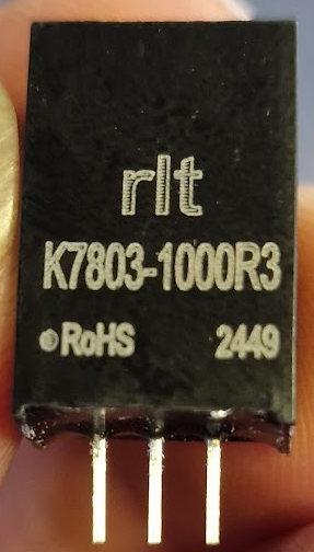
Which specific 5 v regulator did you get?
If it is a linear type, maybe it shut down when getting hot, without heatsink on it.
They should be ok.
How much Amp does your board draw on 12v input
Hi! New user here building my first setup. I have ordered and received the PCB:s from JLCPCB and so far everything seems fine. I replaced the Mornsun regulators with DEXU Electronic ones, and at least voltages when testing with the multimeter seems to be ok (and also F9P is working). Part numbers are:
PWRM-TH_K78XXM-1000R3: C2916516
PWRM-TH_K7805M-1000R3: C909661
I hope this helps somebody with their own project. ![]()
2 Likes
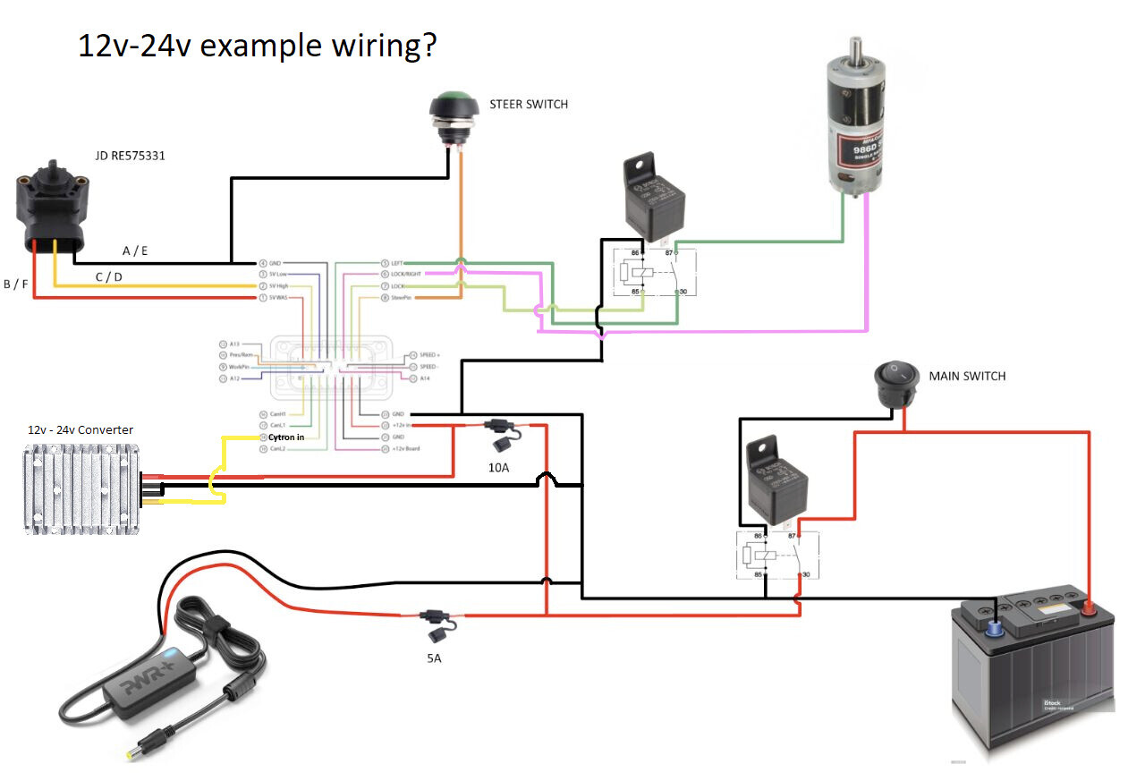
Thanks for all the suggestions. I went back and fixed the soldering and swapped the 5v regulator for 3.3v at the 3.3 position. The teensy took the flashing and I can see it on the software. The LEDs show I have connections. However I am getting some type of feedback and the 12v regulator is kicking off after 30-40 seconds if I disconnect the 12v-24v converter and within 5 seconds with the 12v-24v connected. I checked everything using my second board and it behaves the exact same way with nothing connected to the board and the 5v fuse pulled. I have gone through everything and can’t figure it out. I am using a 12vdc relay and a 12v main switch. These instructions (AIO Ampseal Wiring Harness | AgOpenGPS Documentation) skip the relay and use a 24volt main switch. Could the 12v main switch be my problem?
Are you using the phidgets motor? Are you needing the 24v inverter?
Maybe try it in 12v mode 1st it works fine but no good for uturns
A decent 12v supply to the board. You wont need a 24v main switch.
Ive not connected 24v to the newer boards but i believe you supply 24v to pin 18. Connect your inverter to a seperate 12v supply perhaps and connect the 2 earths together and earth these then the 24v out goes to pin 18 providing you’ve got the additional jumper wire soldierd on the board
I am. I bought the same motor and 12v-24v based on the documentation (followed the links). Even in 12 volt, the relay right after the main switch will still kick off after a short time. However, it doesn’t kick off if the board is not plugged in. But I have had this issue before started soldering anything on the board. It could be in the ampseal plug but I pulled that apart and rebuilt it multiple times and have not been able to find a spot where wires touch. The problem with the decline in voltage resulting in the relay clicking off happens even if the 5v main fuse on the board is pulled out - the multi meter shows the voltage there dropping until the relay kicks off.
So where is your relay and why are you using one?
Ive got 2 systems running phidgets and ive not got a relay.
Possibly its not wired up correctly
Can you show us how exactly is your wiring and your PCB now (both sides)
What you mean with 12V Regulator?
I can add pictures of my board tomorrow - I am traveling to buy seed today. I am following this diagram. The relay after the main switch is shorting out for some reason. Its a slow process when I don’t have the 12v-24v step up connected. It shorts out quickly when I have the 24v step up connected.
1 Like
Put up a picture of your board when you get chance. Ive not used a relay after the main switch but the diagram does look easy to follow.
1 Like
You an use a main switch only, if the switch is able to handle at least 10A (maximum rating cytron) better 16A @ 12VDC.
1 Like
Hi all,
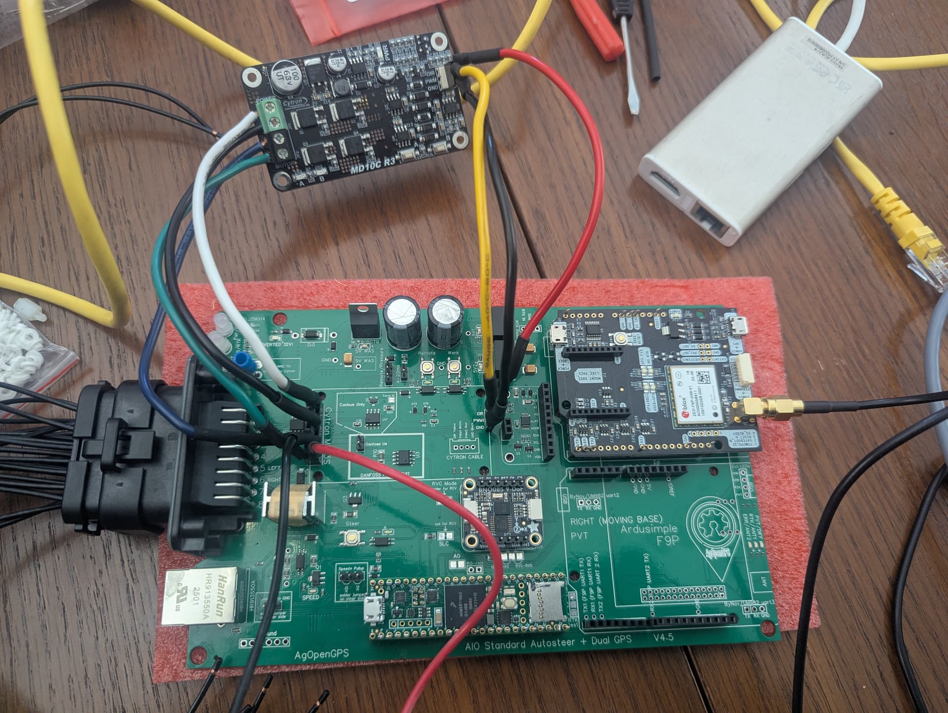
I’m having issues with the V4.5 AIO I’m working on. We have a ZED-F9P, BNO085 and a Cytron MD10C R3 (should have got the 13, but we goofed). We’ve got a decent amount of issues but we simply haven’t been able to advance past getting the GPS working.
We have assembled the board and via the teensy serial connection and UDP, we get a good GPS signal. When the board is powered via external 12V, we have lights on the Cytron as well and the A/B buttons on the board run the motor correctly. The BNO085 has zero lights on it however, and probing it we seem to have around 2.5V on the Vin which surely is a problem. Further, we have not had any luck with the WAS providing a signal (Land Rover sensor).
Summary: we can’t get the IMU and Steering to show up green in AgIO via UDP.
We have followed the steps on the Youtube videos from AgOpenGPS and also the ones from FarmerBrian and just simply things do not turn green. The lights for power/ethernet will go solid green and the GPS one will flash since we aren’t using RTK.
We configured the Teensy with the agomatic configuration thing and are running the AOI V4. We’re running the latest stable release of AgIO and AgOpenGPS. Is our board possibly defective due to the low voltage at the IMU Vin? That doesn’t explain the absence of the Cytron connecting. I compared the documentation of the 13 vice the 10 and I couldn’t see a reason why they wouldn’t work. Motor is a Phidget 3269_3 if that makes a difference.
Looking at your picture I can’t tell for sure but you might retouch the solder on your teensy. It supplies the imu with power. also I cant tell how you have the imu connected but it like kind of weird as well. Usually the imu would sit on top of the plastic of the header pins and then be soldered from the top. Bad connections in those two places could easily be the source of your problems
1 Like