Welcome to the forum
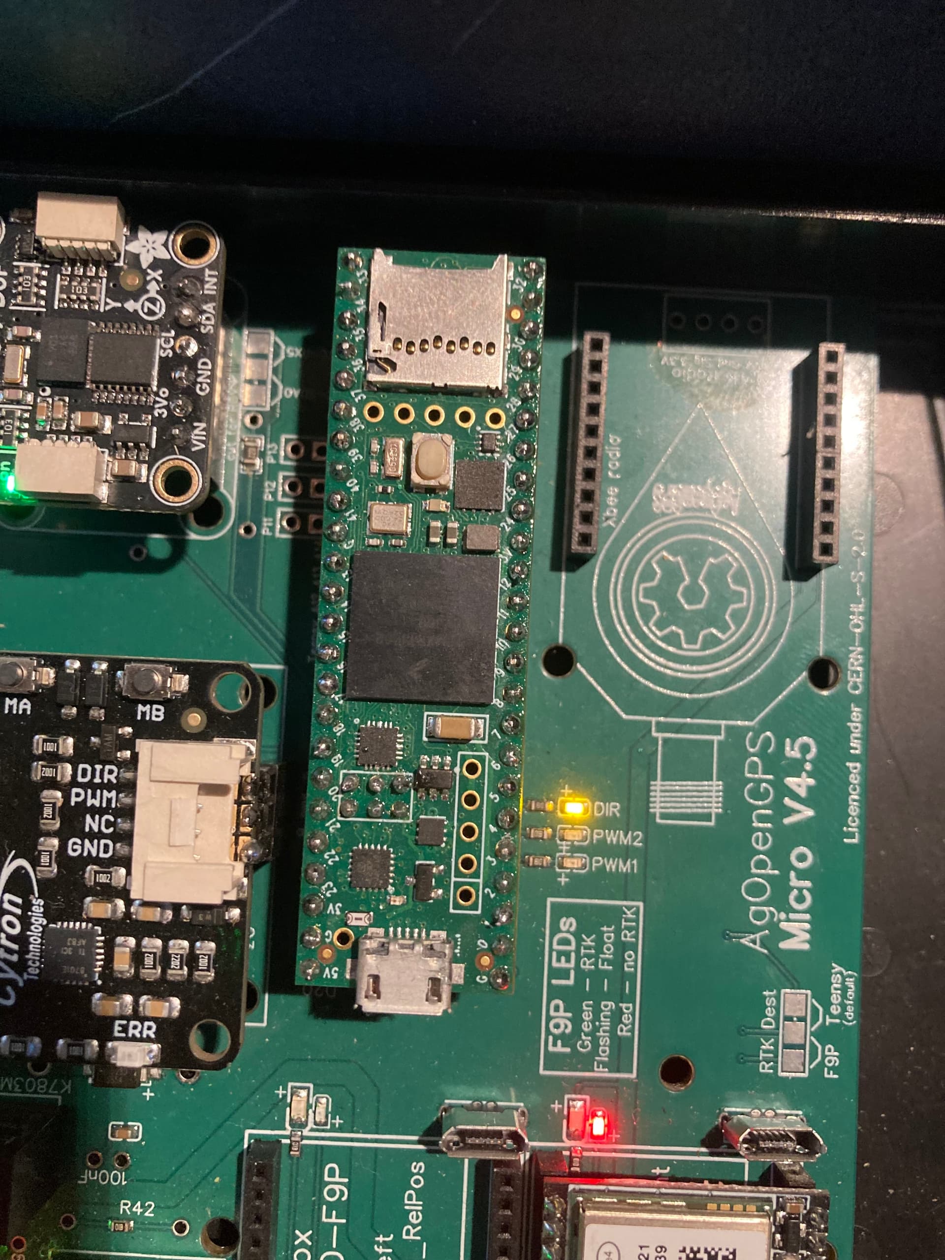
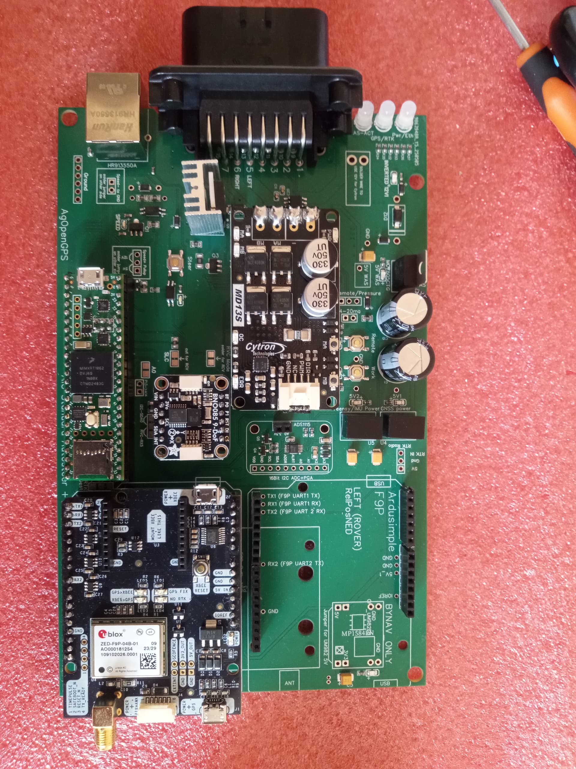
As @cowhound pointed out, according to your picture your solders will definitely cause issues at some point.
Re-solder all pins everywhere with a good solder wire.
I use .020" (0.5mm) wire, some prefer thicker but I like this size.
Watch some Youtube videos first for proper technic.
Thanks for all the help thus far.
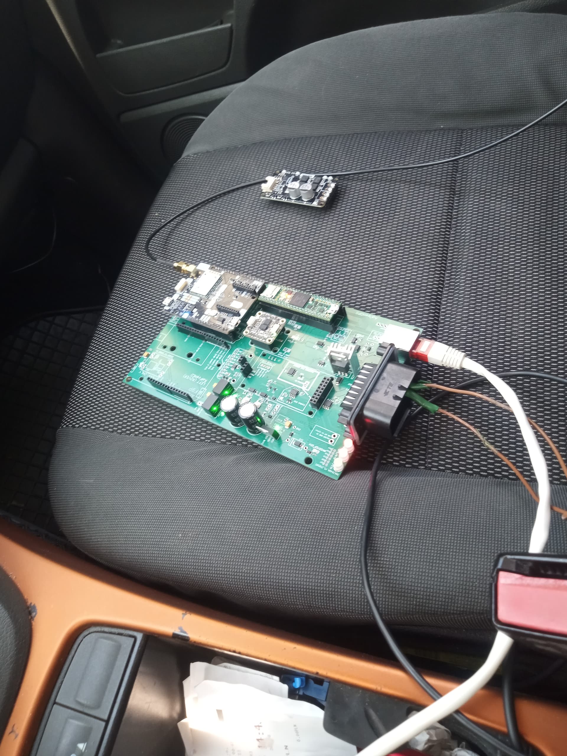
So the upgraded switch solved my power-stability issue.
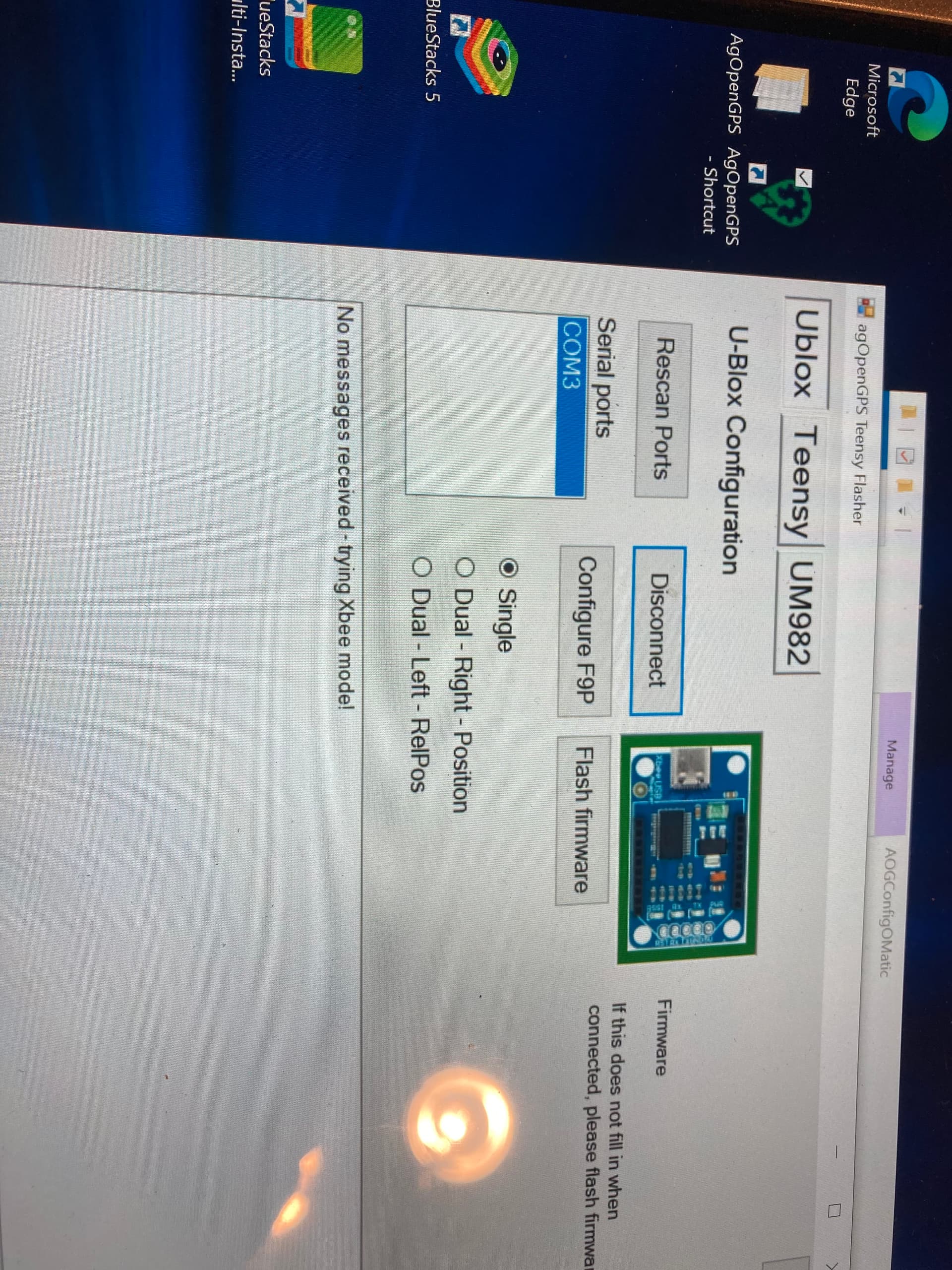
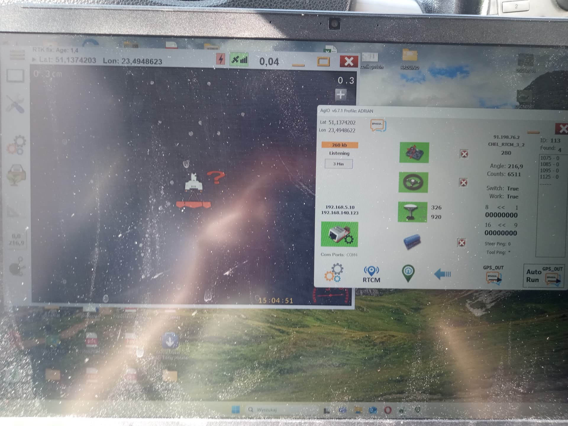
I was able to flash the teensy, the ump82, and ublox (and config) however the led for gps position is not coming on and the led for steer module is not turning green and when I looked at config, it wasn’t finding ump82 nor ublox. I went into my com port settings and windows thinks it is working (the ethernet led is green). Any thoughts on what I have done incorrect at this point?
Thanks again for the help
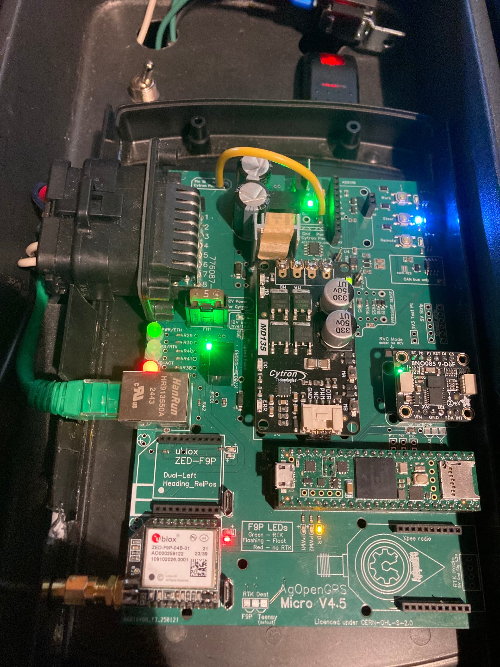
I wouldn’t worry too much about the leds on the pcb they are a bit of a mystery as long as its all showing green in agio you should be good.
Some leds turn green when steer is enabled, one led will only go green if you use dual gps.
Ive not used that little module to configure the f9p, ive only ever connected to the board via the on board connector
You don’t have any ump82, you have a single f9p micro (ublox). For programming and flashing you have to connect your computer to the usb socket near the f9p micro.
What 3d printed enclosures are people using with the v4.5 standard board? Would like to use the pigtail sma connector to bring the antenna connector to the front of the enclosure if possible?
I have my 4.5 micro board up and running (thanks to the suggestions on this thread) but have come up with a question that might not be right for this thread but not sure where else to ask it.
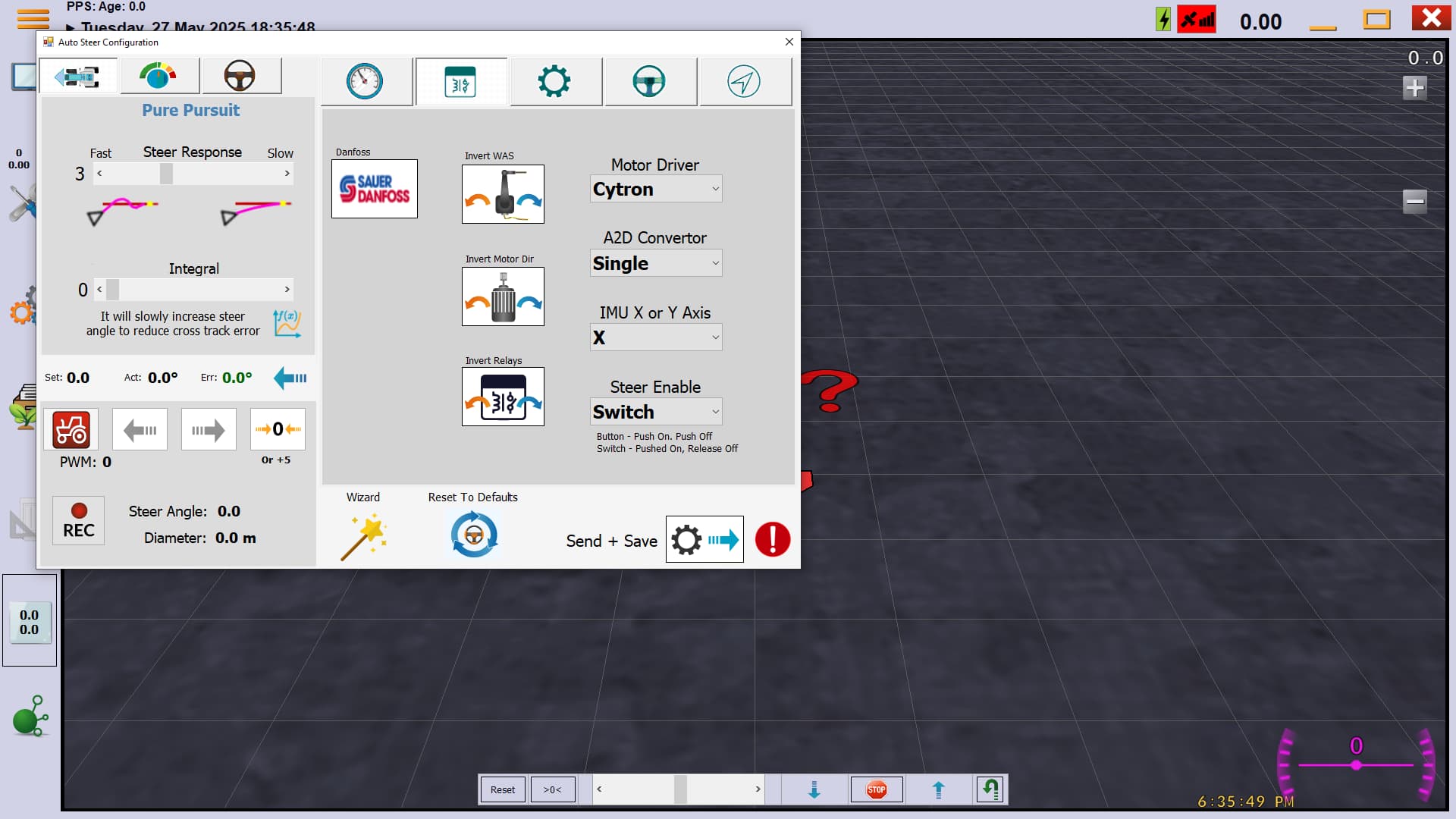
I have been working through “The Steering Wizard” video on the agopengps youtube site posted 7 months ago. Everything goes fine until I get to the point where we calibrate the steering motor. I can’t get the motor to turn the steering wheel when I push the buttons for left or right on the monitor. The board is sending power to the motor in general but not when I try to steer from the screen. When I get to the module I turn the steer switch to where it shows the tractor in yellow in the bottom left hand corner of wizard screen (which agIO says the switch is false when I do this) and the tractor on the screen turns red when I flip the switch the other way and agIO says steer switch is true. But at no time does the motor turn when I press the right or left buttons. Is there another step I am missing to enable to steer motor? Or, is there a good spot on the board to test for correct voltage at the correct time (I am using a 24 volt motor and I have the 12v-24v step up, and I have put the jumper wire on the board to 24v). The angle sensor is reading just fine as is the roll sensor.
Thanks, and sorry if this needs posted elsewhere.
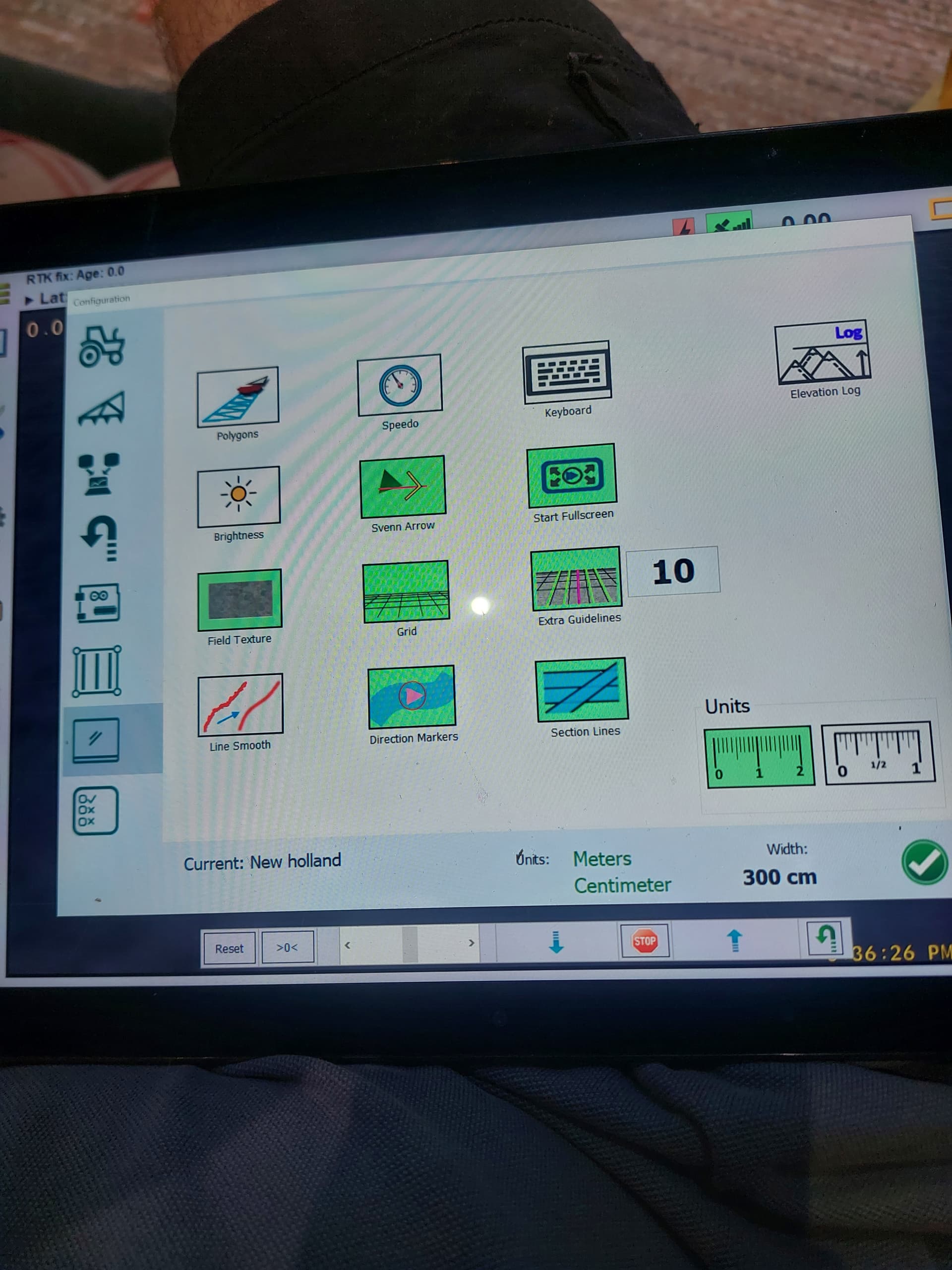
Side question, can anyone tell me how to switch from metric to imperial in the software?
Curious if anyone has steer settings that they use on a New Holland TG series tractor. With a 24v phigets motor.
I cant quite get the steering dialed in. Any bumps in the field really throw the steering around. And it doesnt seem to stay on line real well without weaving around.
Have followed the PWM videos, and have also set a 2.4 board up in a Lexion 760 combine without kuch drama, so I like to think I’m pretty able to follow setup instructions…
When you get to the step where you can press the screen to steer the motor is the tractor icon yellow in the bottom left of the steer wizzard page? If it is your buttons to control the motor on the screen should work.
If the tractor icon is red try pressing your steer button or switch. You need that icon yellow for the buttons on the screen to work.
If you miss that step and go back to it the tractor symbol will be red, you need to go back to the previous step then go forward again (if that makes sense)
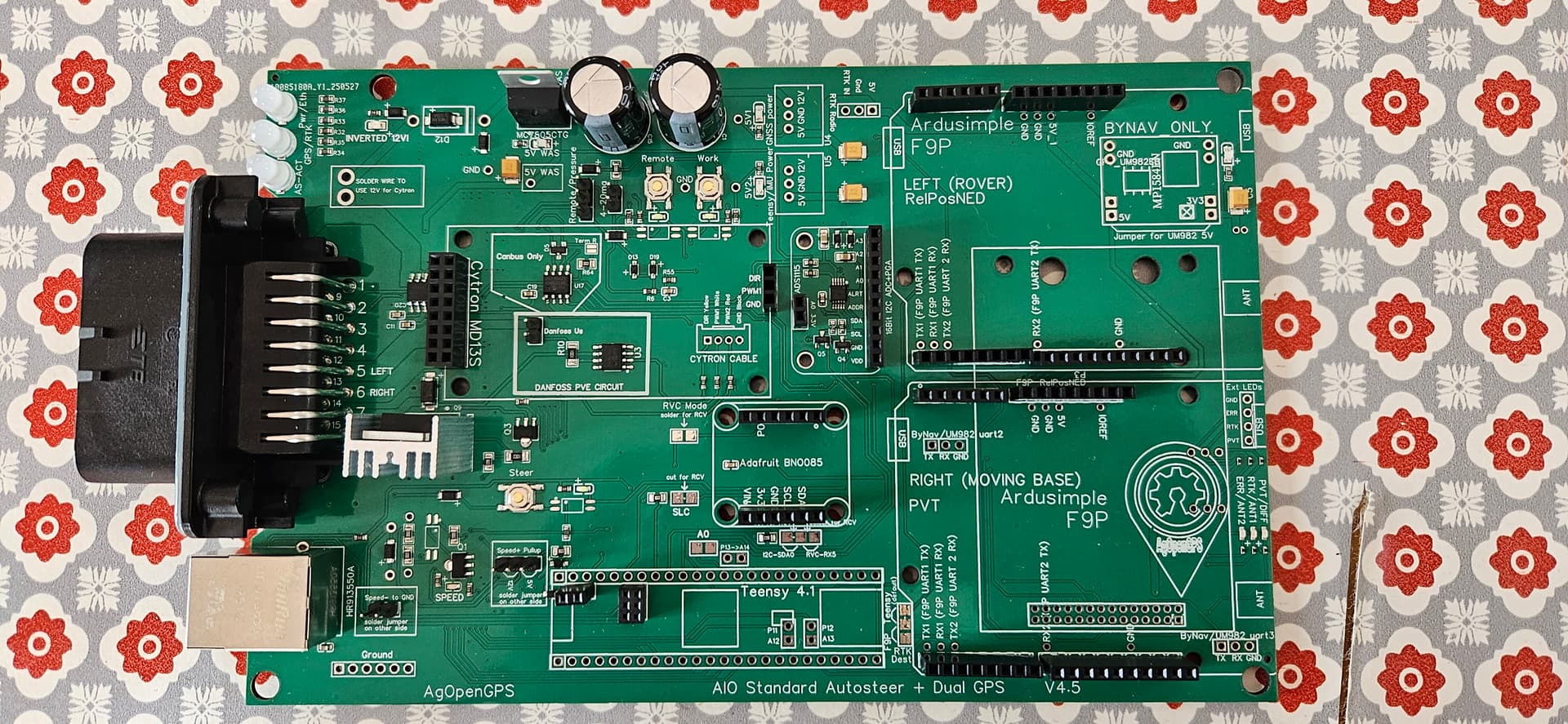
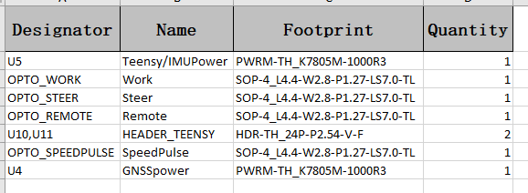
I ordered my first pcb boards last week, they were missing some items but i ordered anyway (mistake 1) i am hopeful that i can add the items but not sure what exactly i need to get. SOP-4 i think are the items missing, also u4, u5 teensy /imu power, also headers for tennsey but these should be straight forward , i hope. Also any advise on soldering in sop-4 didn’t realise they were so small. Thanks
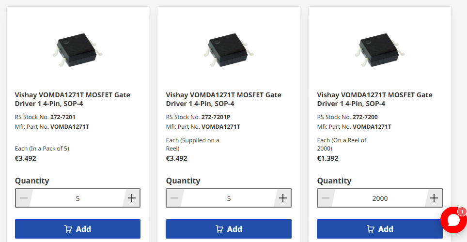
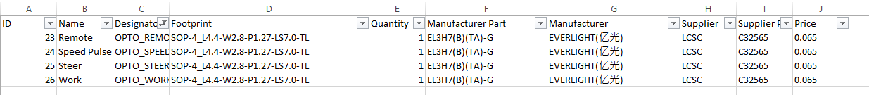
Great, thanks for that, very good video. Would you know if all SOP-4 are the same or do i need to order a particular one, where would i find out which one i need. Same with U4 U5 i want to make sure that i order the correct item. thanks.
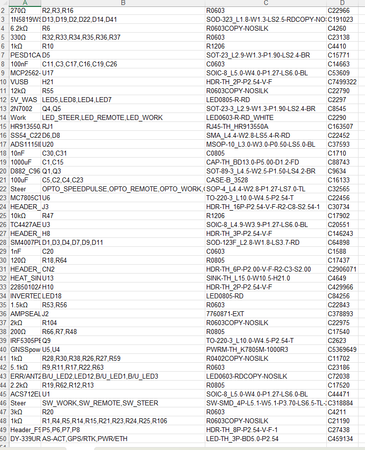
Items missing from my board are listed below. (from JLC order)
When should the rtk/gps led be green? I use ntrip and single zed and LED is Red.
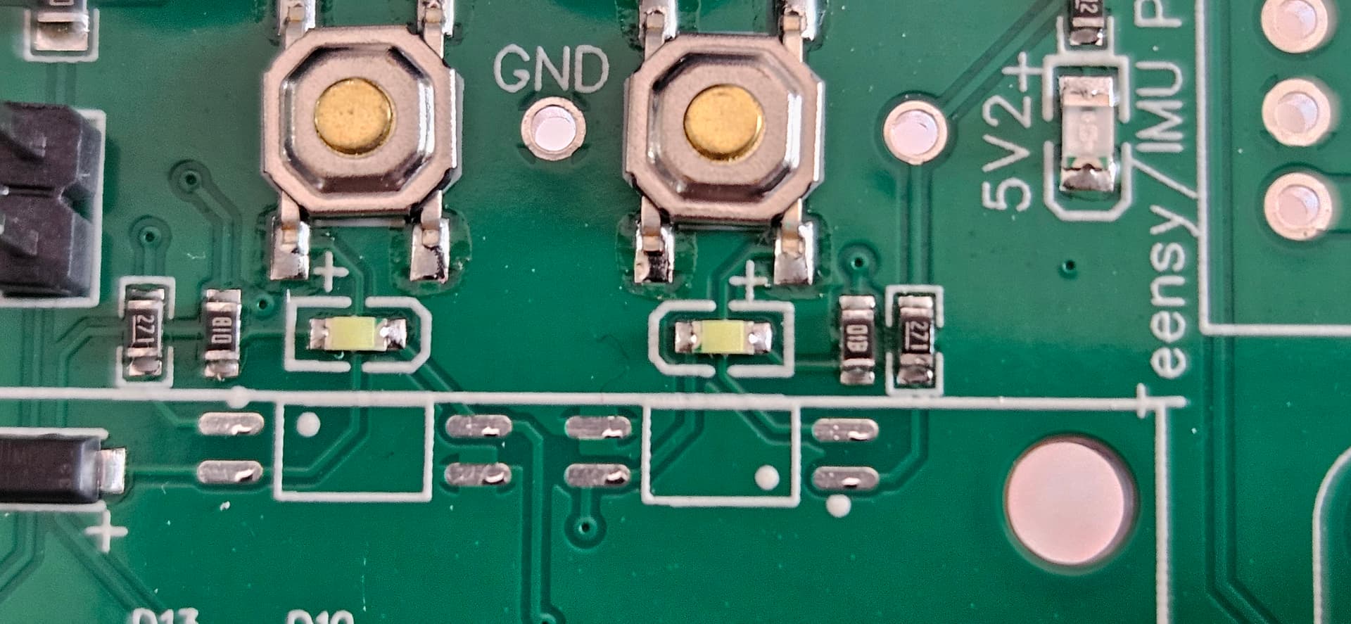
I had trouble soldering the ethernet into the teensy, can you tell from these photos that the connection is ok?
From the picture of the computer screen everything looks good. I can’t tell for sure on the Ethernet pins because the picture is pretty blurry but it is definitely working.