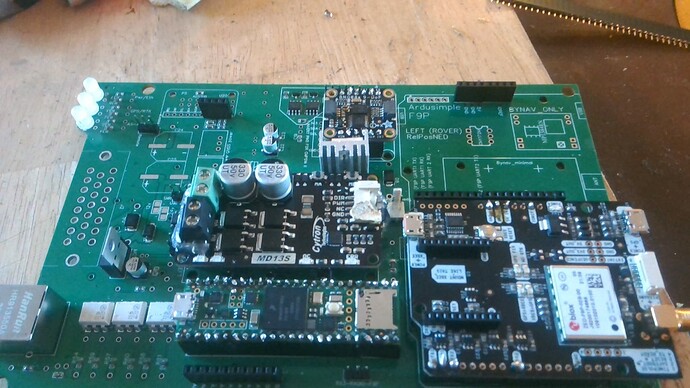
Can somebody show me a picture of the completed wiring of ampseal on their board. What wires do I need coming into my ampseal from tractor? Thank you so much
AMP_Connector.pdf (193,2 KB)
Arek84
So on the tractor side do you just have the following?
3 wires for wheel angle sensor (WAS)
12 volt +
12volt- ground
SteerPin for activate autosteer and Left/Right if you use motor.
i am usinge the v4.2 standard board. Just to make sure I understand, am using danfoss.
1, 2, 3, 4 = for WAS
5 = cytron left
6= cytron right. lock??
7= lock for hydro block
8= activate remote steer switch
9= activate remote work switch
10= pressur sensor for steer off, remote??
11= A12 ??
12= A13 ??
13= A14 ??
14= speed + ??
15= speed - ??
16= can hi for canbus steering
17= can lo for canbus steering
18= alt cytron power, i gues power for cytron
19= ??
20= 12v from board example for UDP switch and other components that go together with the autosteer board
21= GND from board
22= 12vv to board
23= gnd to board.
Where ?? I do not understand.
for my situation I need
pin 1/4 for the WAS.
pin 7 for 6/2 hydro block
pin 8 for remote steer
pin 9 for remote work
pin 10 for pressur sensor for off steering
pin 23 GND in
pin 22 for power in
pin 21 for gnd
pin 20 for power upd switch, rate controller
but where i connect my 3 wire danfoss??
