EKF or UKF are also used in Drones and unmanned vehicles firmware like Ardupilot and PX4, maybe someone can take some sort of inspiration
This is where the WAS less concept really helps because in that scenario actual steer angle isn’t having the effect AOG is expecting whereas WAS less does. I’m pretty certain it would still be correct for side mounted equipment too, which has a totally different effect on steer depending on whether the implement is above or below the tractor in relation to the slope…
1 Like
Hello,
At the beginning of this year, I’ve suggested to the development team to add a data log function exactly for this purpose (this idea came to me when I was testing bno085 last year, such fonction would have help me).
I was thinking a log function have been added into v5 with AgIO, was’it ? (I haven’t switch to v5 for now).
Math
1 Like
Yeah, gotta check. But I have a feeling it’s only recording the traffic, i.e. NMEA and roll, but not the whole IMU output.
This will be HUGE if made to work well !!! Essentially be able to eliminate steering slack issues!! This theory is how the big JD systems work many do not use a WAS at all!!! Wish I could contribute !
Trimble does not use a WAS, but they did dedicate the first 10 pages of most of their manuals to identifying and fixing slack issues in steering.
Loose steering parts are random deadband. Random is a very hard thing to control. I would not expect a vast improvement with either control scheme without first fixing mechanical issues.
2 Likes
Are you talking about the ATU system? Regular built-in autotrac does use WAS.
The built-in Trimble systems that use the NAV II or NAV III controllers also use WAS, but @PotatoFarmer is right that the EZ-Steer and the steering-wheel replacement units do not and they work quite well for the most part.
Sounds like they use an encoder on the steering wheel, though? If so, all slack goes to measurement uncertainty.
Got now an idea for the filter for the yaw angle, that estimates the gyro bias, still need some thinking with the yaw rate.
Yes I was refering to ATU I guess my point was more to ease of installation with a WASless system!
I’ve done a fair bit of driving around with my very basic WAS less code and the most apparent finding is that any kind of filtering that uses historical data (with its inherent latency) is a big no no. As speed increases this effect becomes increasingly significant. IMHO rogue value rejection is how filtering is best implemented.
Yaw rate isn’t something that changes significantly at a high rate but it’s changes need to be registered immediately for decent steer.
3 Likes
A WASless system requires an encoder on the steering wheel whose data is essential to estimate the degrees of steering and to be more precise. This can also prevent play in the steering joints which can affect the steering precision of a was.
That to me is basically pointless, in the scope of what I was trying to achieve anyway. If you’re putting a sensor anywhere it might as well be on the steered axle. Wheel encoders are of limited value on hydrostatic steer as there is inherent slip and creep in the system that basically adds difficult to quantify error.
Neither of these sensors give the absolute yaw rate we are looking for.
4 Likes
Agree, you can’t use averaging. But a good Kalman filter is a different beast, it uses a prediction model to check the feasibility of measured values and then decides which values to use for the update. I checked you code and the bump rejection is a good idea, dead simple. Why it (probably) works is that the pitch rate also has an effect on yaw in the reference coordinate frame when there’s nonzero roll or pitch of the vehicle. The motivation is to use GPS heading to get rid of the sensor bias.
Looking at CPU power of Teensy, should be no problem to run a real time filter, especially for yaw only.
1 Like
I did try a simple kalman filter (in the code I think) but found it better in difficult conditions without it. Not sure if it’s enabled or not in the code I posted. I have that many versions ![]() . I always seemed to end up back at the most simple code.
. I always seemed to end up back at the most simple code.
I haven’t had time to look at it for many months but I still think it is an interesting and probably more accurate method in less ‘easy’ field conditions.
On a prairie with wide tools pretty much anything will make a good job and seem fine. In the sort of conditions / tool sizes I, and many other European farmers have to deal with, the tech has got to be more intelligent.
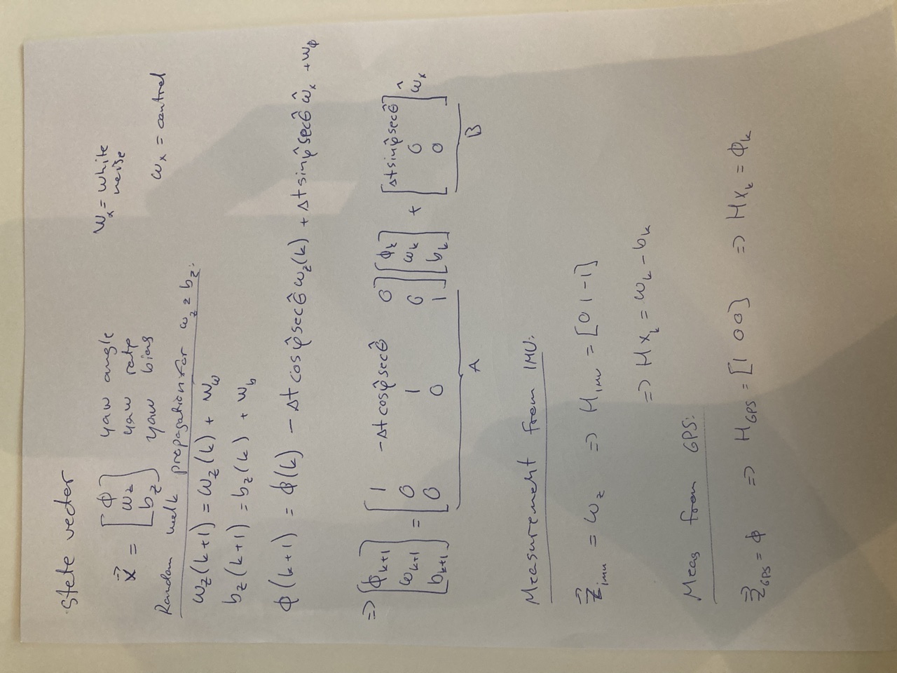
This is what I had in mind for the filter. Basically it’s using the roll / pitch rates and angles directly from IMU, and running an estimate for yaw angle, rate and bias. Just need to figure a sensible way to estimate the covariances and test it out.
The cosines etc. come from the transformation from IMU to navigation coordinates. Two different measurement models can be run at different rates, use the IMU data to update the rate & bias estimates at high rate (50 Hz possible from BNO08x?) and run the GPS update at 8 Hz. So it will need the GPS data coming into the Teensy as well, probably needs some switching rule for the GPS update in heavy cornering.
So in short the idea is to use the yaw angle to calibrate that against the yaw angle from GPS to resolve the gyro bias and then just keep running an update for the yaw rate with the bias removed. Makes sense? Don’t know ![]()
2 Likes
Hello,
Yes, up to 400hz for Game Rotation Reports, if only this report is active. And assuming the I2C bus is able to support this communication rate (depend of the speed of the I2C bus).
Math
1 Like
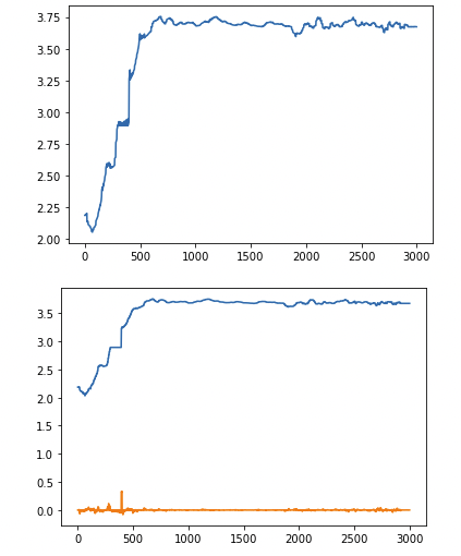
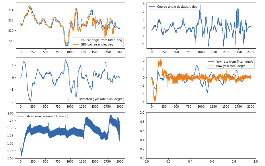
Got first rid of the yaw rate as a separate variable, and reduced the system to yaw angle and bias. So now it’s using the pitch and yaw rate as control inputs to the filter. Actually, it was just one set of brackets missing in the 3 variable code and that works just equally as this one. Just have one set of test data for now, but some results:
Here’s the integrated course angle from accelerometer pitch and yaw rates, with a filter update with 5 Hz GPS heading. First pic integrated, second GPS “true course” at 50 Hz (but the filter is using it only with 5 Hz rate, i.e. always going 10 steps in between with IMU integration.) and the error between the two
This is what it looks like with pure IMU integration:
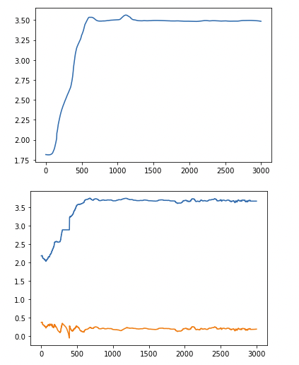
And then the yaw rate values, first the yaw rate bias calculated by the Kalman filter and the second pic comparison of raw yaw rate measurement and the bias corrected (orange and blue lines, respectively)
Very preliminary, but at least it gives something reasonable. All the variances are just pulled from the sleeve for now, need to figure those out properly etc. Maybe use the GPS estimated position error and velocities to scale the measurement uncertainty. Process noise based on sensor characteristics and system matrix. And get a better dataset with known sensors, just pulled the csv data off from one of the linked articles above (Balzar et al)
2 Likes
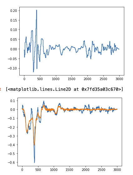
And some progress with the 3 DOF state vector version, using now the GPS estimated position error as a scaling factor for the GPS angle estimate, need to refine those still a bit and set some tuning parameters, maybe add the GPS speed to the equation as well. At least the mean square error is now making sense so should be quite OK. Running IMU update at 50 Hz and GPS at 5 Hz in this one:
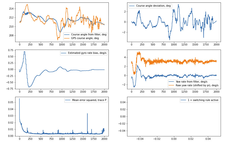
UPDATE: And oh what a difference a bit of filter tuning made ![]() Set up the process variance as it should be as a timestep dependent matrix and calculated a rough variance number based on max vehicle angular acceleration of 80 deg/s^2. Bias variance set as 10^-12. Measurement uncertainty for IMU assuming 0.5 deg/s bias and for GPS angle uncertainty usings GPS EPE^4. Shifted the yaw rates a bit for easier readability in the figures, the curves sit on top for the yaw rate. Basically it’s now trusting the model more and regarding the GPS heading jumps as gargabe, as it should.
Set up the process variance as it should be as a timestep dependent matrix and calculated a rough variance number based on max vehicle angular acceleration of 80 deg/s^2. Bias variance set as 10^-12. Measurement uncertainty for IMU assuming 0.5 deg/s bias and for GPS angle uncertainty usings GPS EPE^4. Shifted the yaw rates a bit for easier readability in the figures, the curves sit on top for the yaw rate. Basically it’s now trusting the model more and regarding the GPS heading jumps as gargabe, as it should.
9 Likes
Wow. I’m amazed by the smart people on this forum!
So once a reliable yaw rate can be determined, will that be a substitute for the steering angle? I suppose you could easily calculate a virtual steering angle, but maybe just the yaw rate is good enough to work with pure pursuit?
It occurs to me that I was sorely mistaken about the applicability of this work to terrain compensation. On the contrary, if the IMU through your math and filtering, can yield a reliable heading (and faster than the one you get from GPS), that would allow more accurate terrain compensation. Which brings up an interesting question (perhaps chicken vs egg), would the heading get even more accurate if the GPS portion of your code was fed by the terrain-correct GPS position? Or is it best to just stick to using the raw GPS calculated heading (perhaps filtered) even though the machine rolling over bumps and waving the GPS receiver back and forth would introduce some oscillations into the GPS-calculated heading. Hope that made sense.
4 Likes
As for the steering angle, you can convert it either way. Either calculate the virtual steering angle from yaw rate or target yaw rate from AOG (which is already calculated by AOG as noted by @BrianTee_Admin earlier in the thread) like this:
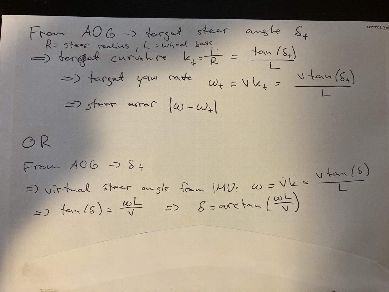
@Alan.Webb used the virtual steer angle in his code, using tan x = x as approximation.
As for using IMU + GPS fusion, yes you vould do it for the position and velocity as well, just increases the system size. Roll and pitch seem to work decently with the 6 DOF fusion taking place in BNO already.
1 Like