Me too! This is above me to be honest but still very interesting. I took a simplistic view given the quality of the BNO085 output and also the actual vagueness of a standard WAS on anything but very stable very flat ground.
2 Likes
It’s still the same simple working principle, just using a bit of extra data available to make the yaw rate signal more reliable. In the same way you could fuse the GPS speed and IMU acceleration sensors to get a more reliable speed value. Of course it needs a bit of extra hassle to get the GPS data to the Teensy.
The filtering is maybe a bit misleading name as what the Kalman filter is doing is a prediction step based on the model, i.e. integrating the gyro signal to get the yaw angle and then a correction step based on the measurements to update the estimate. On both steps it’s updating the covariance matrices, i.e. the algorithm is trying to figure out which it’s trusting more, the measurement or the model. So if you get a big jump in GPS, it’s reflected in the GPS yaw variance which goes up, hence the Kalman filter is trusting more on the integrated value from the model.
Why we’re interested in the yaw angle in the model, is because that’s easily measured from GPS. From this we can calculate what the difference between the vehicle heading and the heading computed based on the gyro yaw rate is, and this is how you end up with the bias estimate. So the yaw angle is just a means to an end to get a better estimate for the yaw rate.
4 Likes
So this could be used for the GPS+IMU heading fusion?
Yes, that’s what it’s doing basically.
1 Like
this is cool !!! I understood it was for the was less in the teensy, sorry
Well, it’s doing both of the things at once. The filter is for getting a better yaw rate estimate, but as a side product you get a fused IMU + GPS heading estimate
2 Likes
Some results now with BNO080 on desk setup, just a short set of data of first a yaw motion, then pitching, then rolling, then roll/pitch pose yawing motions. Here with constant covariance matrices:
Here scaling the IMU variance with the pitch rate:
You can see in the pic below that the signal is getting smoother during the pitching motion as it’s trusting the IMU less, which is reflected in the mean square error as well. Getting slowly somewhere… Next maybe move the filter to the Teensy, now I just recorded data and ran the filter on python. Of course it’s bit cheating as I used the BNO heading angle to replicate the compass for now, just to see that the fusion algorithm works OK.
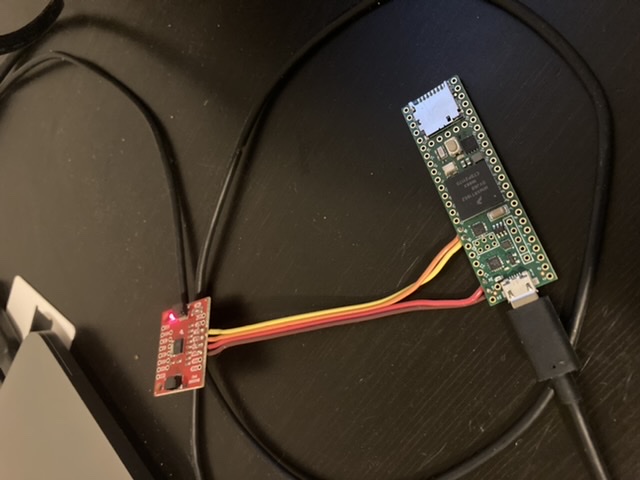
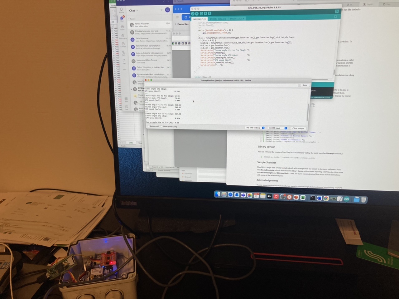
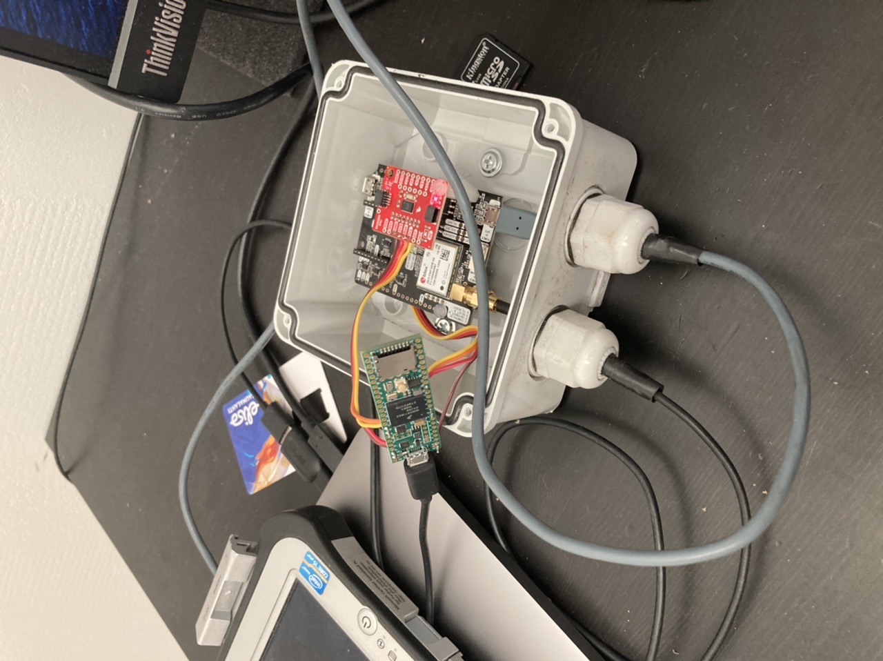
Professional test rig:
1 Like
Alright, the testing continues, still had some sign errors in the code. Now it should be correct finally, and also took into account the coordinate transformation from IMU coordinates to the navigation coordinates, i.e. take the rotation matrix and calculate the yaw rate from gyroz and gyroy rates.
Now, the interesting bit. Here is the corrected version with the process covariance matrix (i.e. how reliable the model is) calculated from a maximum yaw acceleration of 80 deg/s^2, which would be a max value for passenger vehicles.
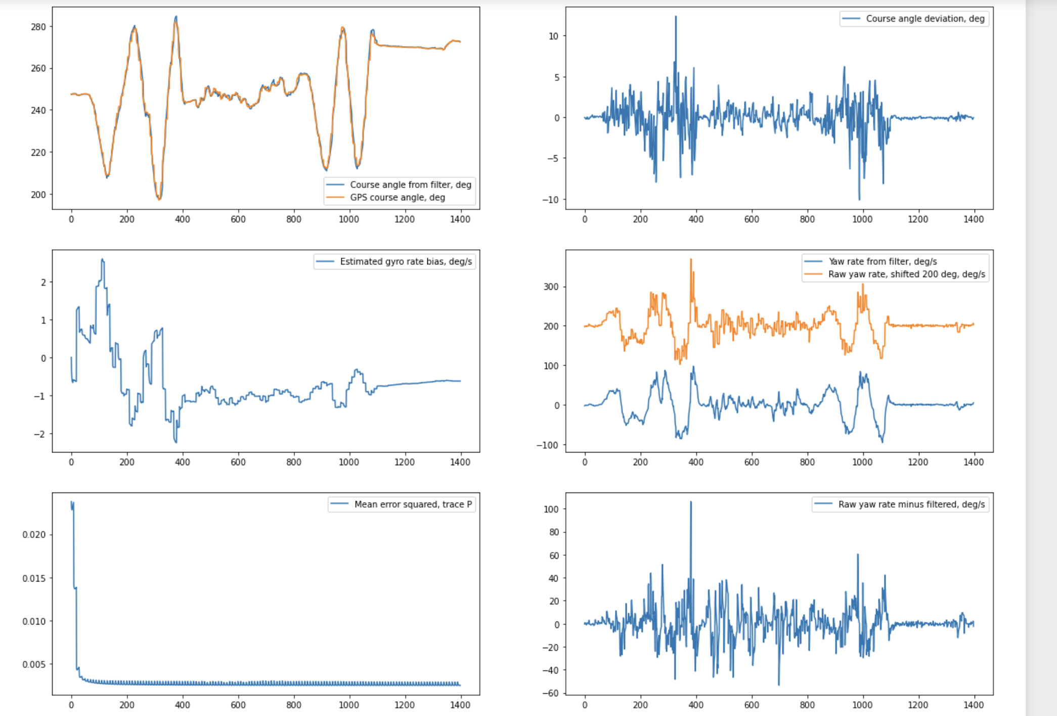
Now, that value is rather high. So I took from @Alan.Webb ino the yaw acceleration limit value of 0.075 rad/s^2, roughly 5 deg/s^2. So taking that same value and scaling the process uncertainty with the square of the ratio, we get:
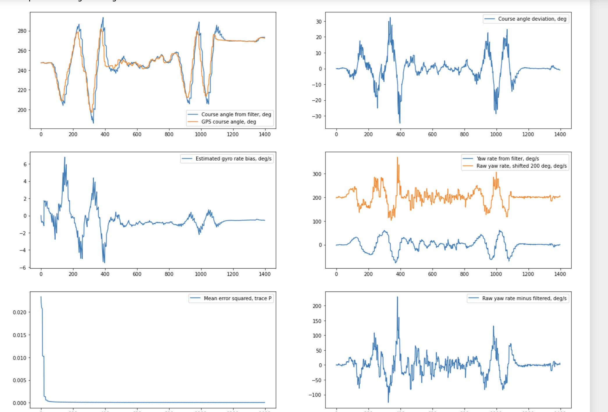
PIcking an intermediate value, say 10 deg/s^2 for the angulr acceleration of the tractor, we get bit more of the dynamics back:
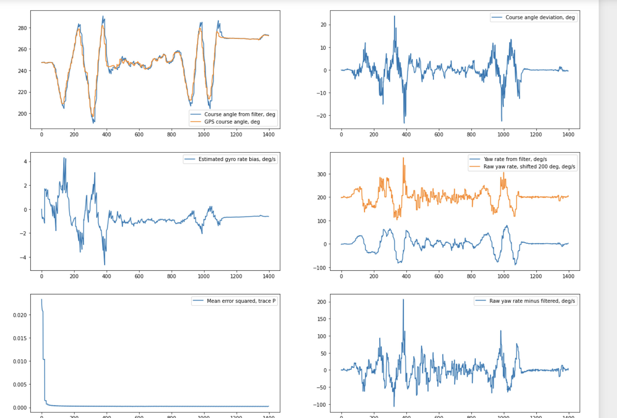
Of course this is just me waving the BNO080 around over the desk, for real filter tuning need to hook it up to the machine.
4 Likes
Really interesting. Doing my best to understand!![]() .
.
Waving around on a desk Looking at graphs is how I played with ideas. Made it a lot easier to see any latency too.
Some HW mods as well, hooked up the F9P to Teensy via UART1 and wrote some code for rhe heading calculation. Using TinyGPS++ library for arduino and parsin the GGA + VTG for speed and heading from fix to fix as well as the VTG course made good data.
2 Likes
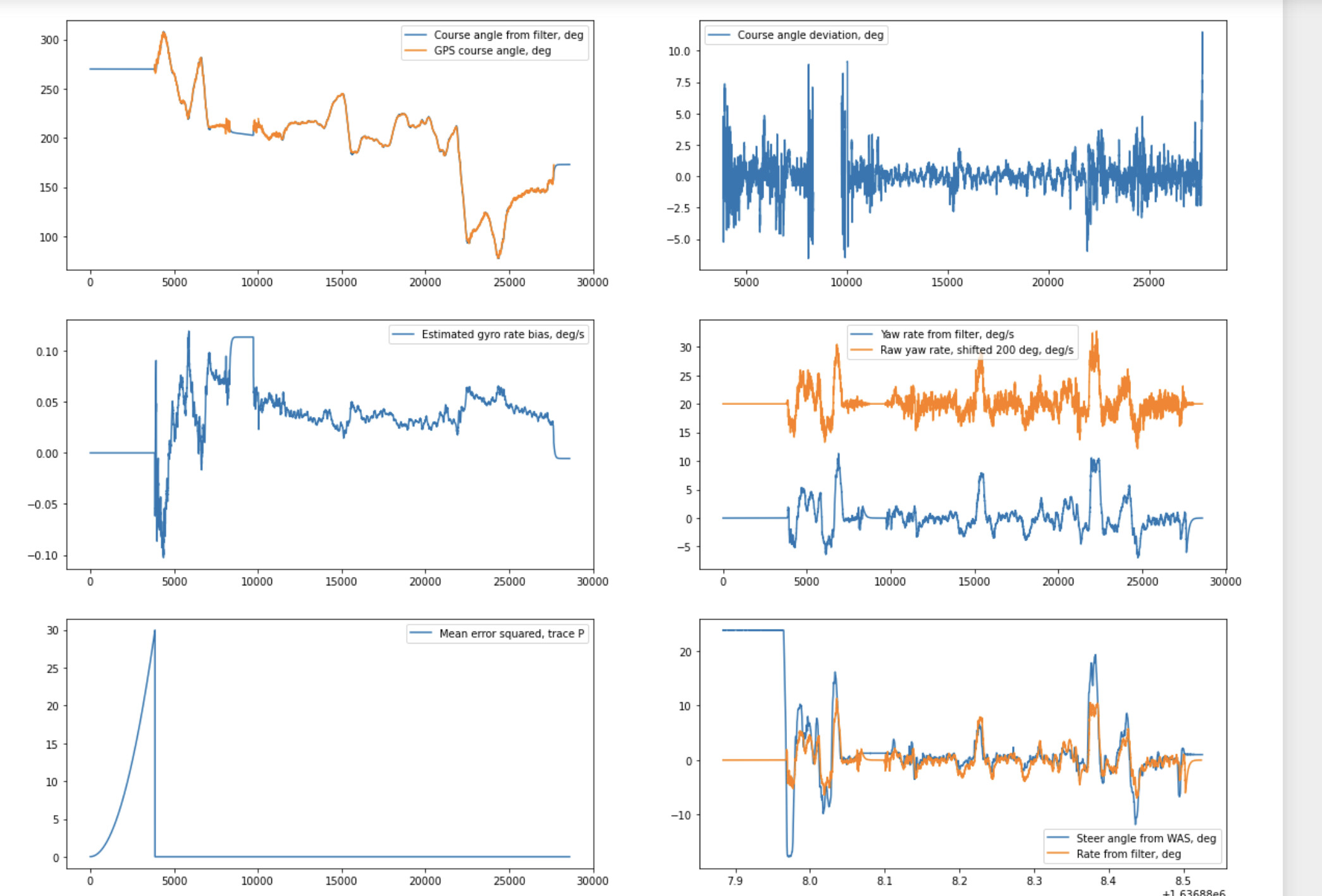
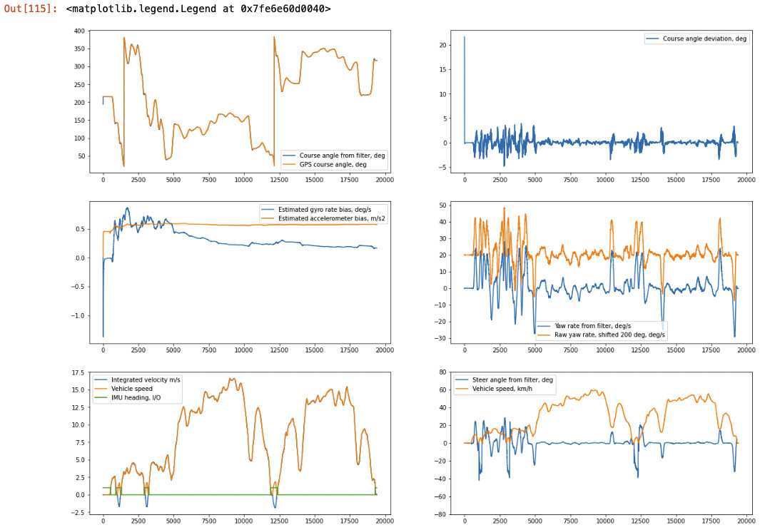
Okay, some tractor data now. We did bit of testing on @Jussi New Holland with the wheel angle sensor hooked up and then the GPS + IMU stuff on a bracket in cab. Signal was dropping at times to float with the antenna inside the cab window. Of course I forgot to log the GPS speed so can’t do the exact scaling ![]() But if you take around 3 meter wheel base and around 10 kph that’s around 1-1 conversion from rate to wheel angle, so not that far off. Anyway, this is with taking the heading from the GPS VTG signal, doesn’t look too bad. Lower right corner is the comparison between IMU calculated steering angle (missing the speed scaling) but seems to reproduce the steering angle pretty well! So this is NOT using the IMU heading at all. Parts of it we were driving in the middle of small forest patches, public road etc. so not even idea field conditions, or course not ultra jumpy ground.
But if you take around 3 meter wheel base and around 10 kph that’s around 1-1 conversion from rate to wheel angle, so not that far off. Anyway, this is with taking the heading from the GPS VTG signal, doesn’t look too bad. Lower right corner is the comparison between IMU calculated steering angle (missing the speed scaling) but seems to reproduce the steering angle pretty well! So this is NOT using the IMU heading at all. Parts of it we were driving in the middle of small forest patches, public road etc. so not even idea field conditions, or course not ultra jumpy ground.
The first blank line is me trying to figure out how to put a NH in reverse most likely ![]()
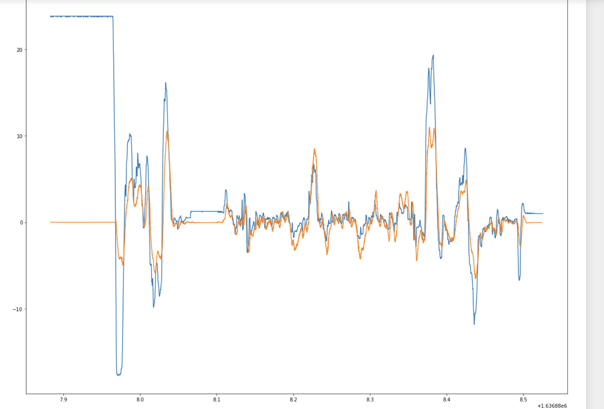
Here the WAS-“IMU WAS” signal comparison with more resolution, like said, speed scaling missing so they can’t be on top of one another but the shape matches well = dynamics seem correct:
4 Likes
So you may be killing two birds with one stone. If you can steer reliably off the IMU for WASless steer, and have tamed the signal enough it pretty much follows good RTK, on loosing rtk full switch to imu should keep it blindly following its path, only wandering due to bias drift. Kinda like leading a blind guy to his front door, and letting him loose in his house, from last known position he stays the course.
AOG Extend without having to fall back to satellite.
1 Like
Yeah, now it’s doing that for the yaw and heading only, like in the above example when the GPS drops. Would just need to extend the filter to the position and velocity variables as well for full sensor fusion.
Need to modify the teensy code for NMEA parsing, lat/lon comes through somehow garbled and/or laggy. Maybe it’s the TinyGPS library losing accuracy in significant digits. Maybe easiest to take thr fix to fix code from AOG base and parse thr NMEA manually.
Small update once again, fixed my data collection code and ran a quick test with my car on the road:
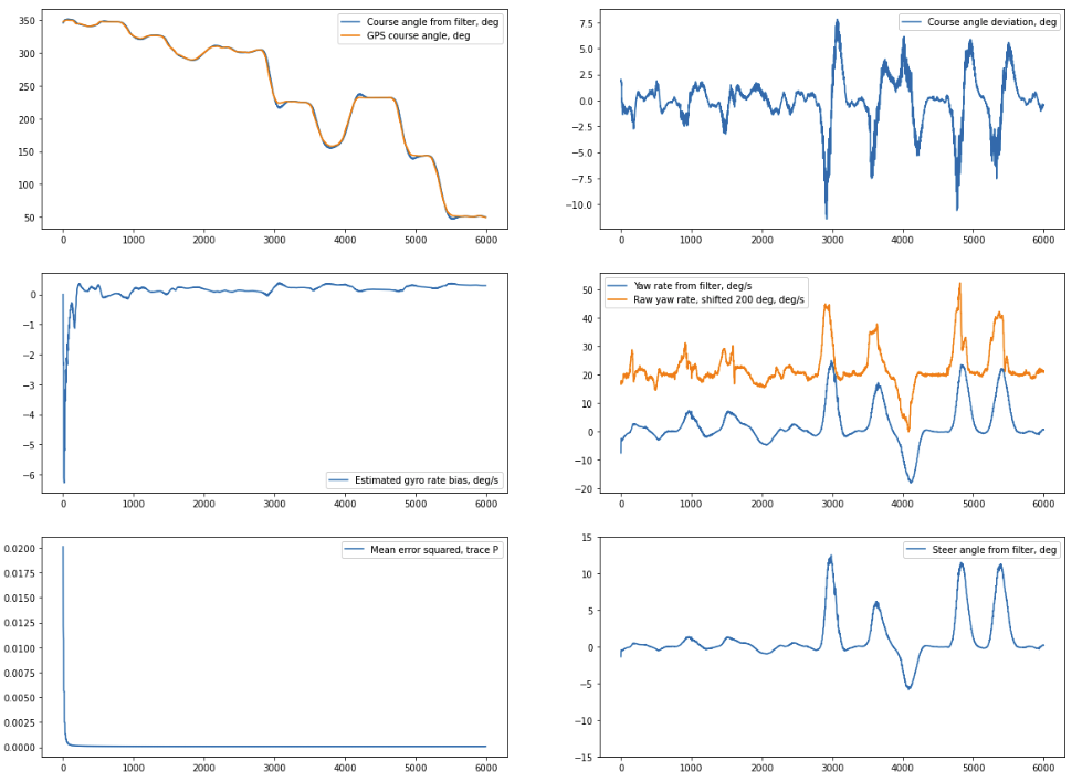
No steer angle reference, but look reasonable. Still need to tweak the code to understand the heading jump from 0 to 360 deg being the same thing and then dump it to run on the Teensy, slowly getting there…
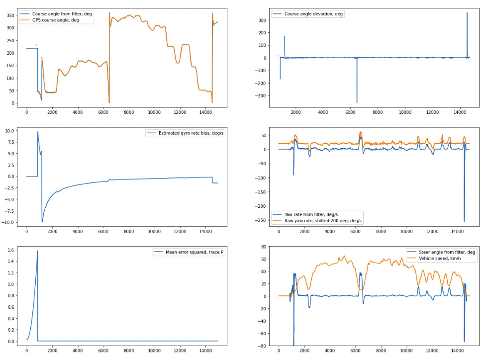
Here with the jump handling included and bit more carlike parameters. The initial jump is when the direction changes when I’m backing up in the yard, midway there’s a u-turn and finally the last jump is a slippery corner where the door handle was moving in the direction of the velocity vector ![]()
6 Likes
Looking great!
What about reverse detection?
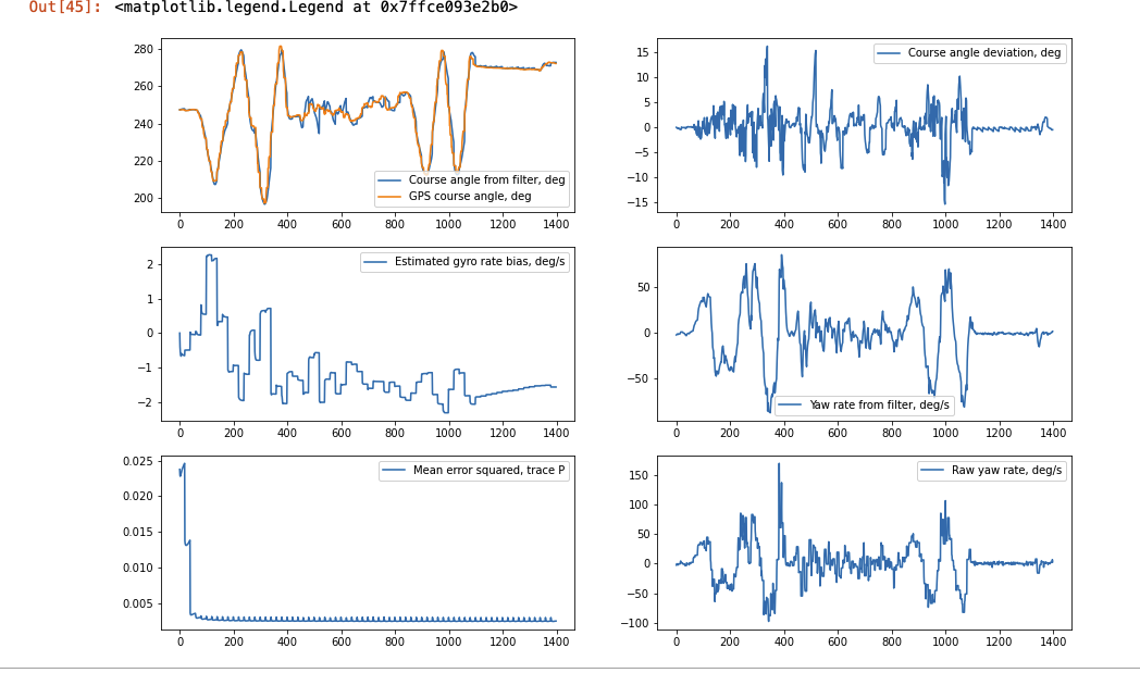
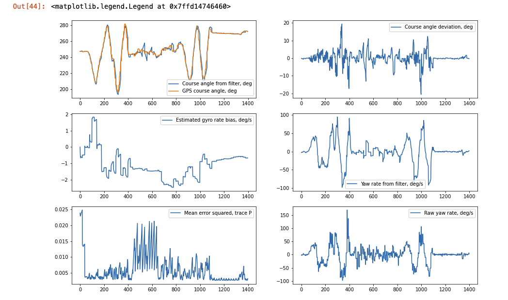
Like so?
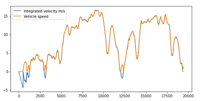
First try at fusing the accelerometer signal with GPS speed, not using the heading at all. When speed drops below treshold (1.0 km/h in this example) the filter stops using the updates from GPS and runs purely on IMU, works at least for brief stops, should maybe add a lower tolerance to set the speed to zero when the GPS speed is close enough to zero. The heavy drift in the beginning is from the offset of the accelerometer that isn’t fixed yet as it doesn’t have a speed reference yet. Then it changes the sign of the GPS speed depending on which way we’re going based on the integrated accelerometer signal.
7 Likes
do you mean that when it goes from 0 to 360 and vice versa, the filter has a jump?
Yes, now got it (hopefully) working. If you just force the variable to [0,360] the Kalman filter goes nuts in rapid changes, modified the code to give a continuous heading (i.e. track when it jumps and keep track of the current shift and then recomputes correct heading with the shift) so that you don’t get artificial jumps into the yaw rate. Also modified the code for the reverse detection to add the zero speed forcing and now using IMU heading when going below threshold speed and going in reverse. Now it makes sense for the WAS reading even when going in reverse.
The BNO080 heading is very very stable, basically very little difference if using that or fix2fix heading from RTK. However, with RTK you get the trajectory of the vehicle instead of where the nose is pointing.
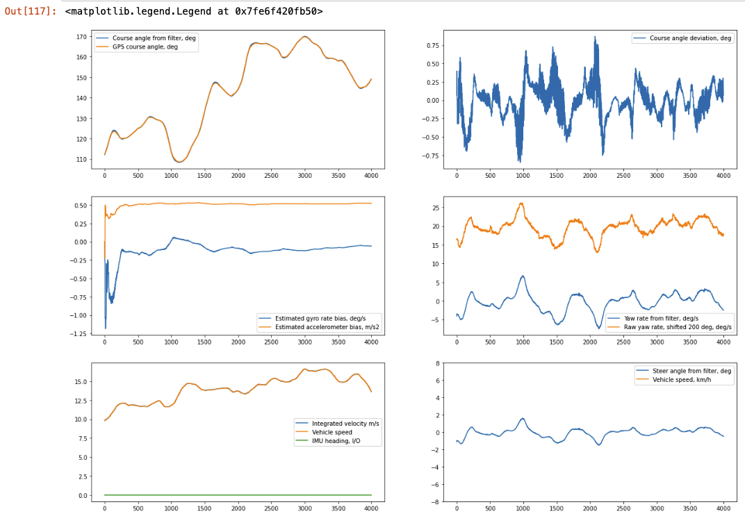
Here’s a zoomed snapshot when driving straight on the road, index 6000-10000 in the first pic:
6 Likes
While you’re building out code to do all this awesome integration and filtering, any thoughts on a simple way to calibrate the IMU for zeroing out the roll? I’m partial to the John Deere method where you drive straight in one direction, stop, press a button that captures a reading, then turn 180 around and park on the exact same spot, in the same wheel tracks, and press a button again, capturing the roll again. The roll zero point, then, is the average of those two roll measurements. That way if the IMU wasn’t mounted perfectly, it would still work great, within certain tolerances of course.
Maybe a couple of buttons and a couple of LEDs could be a sufficient interface.
Also do you plan to put any code up somewhere? I’d sure love a peak at it and use it to try outputting NMEA that is corrected for roll at heading.
Reichhardt also requires that kind of calibration before starting as you said. Regrading zeroing the IMU (roll, pitch), Isn’t it just enough to get those offsets while you stay on the flat concrete?