Can I just check something- would I be right in saying that if I’m playing on powering the relays from the 12v 3 pin in the tractor, I will also need to power the tablet off the same location so that the grounds are if the same source? Also do you need a step down to power a 4 sections relay?
Just my plan is to have the option to control the sections via a dpdt switch but also run agopen in auto
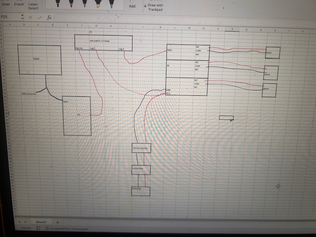
Picture too small to read.
Why do you need step down to power relays? 12V relays work from 12V outlet without voltage conversion.
Powering tablet? If your tablet charger is 12V then it should work.
Usually tractors have same ground for all 12V systems. You need separate ground if you have 12 and 24V mixed system and want to take 12V from 24V battery. Then that second virtual ground is 12V of 12 V battery and don’t get along with 12V battery ground.
I couldn’t put up any larger due to file size- not about to pinch and zoom on it?
So I was advised to drop down if it wasn’t to much hassle, main due to if I planned on having my tablet charging of the same 3 pin- making reason was to keep all the same grounds?
The tablet should power the nano and a 4 relay board ok without anything extra .
The relay board will need to be 5v though as that what the nano outputs
If you like to use switches in case for “without agopen” you need to wire:
power 12V -----> switch ON/OFF ----> your relay-NC-contact ------> to section valve.
Think that be on a simple on off switch’s I have a on/off/ on, on1 is for auto so the nano controls the relay, then off and then on2 is for the relay 1 to activate valve 1?
Or am I just making this more complicated than I think?
Have seen switchbox between relay board and implement. Then can override relay. Don’t know if 2 position switch is enough. Probably 3 position switch can turn off, manual on, input from relay board. ON-OFF-ON switch
Yeah I’m working with a 3 positions switch. The initial guide on the wiki seems to be just using the nano to power everything- I’m trying to essentially make it run along side ag open or have the option of running it manually. I’m going to have the relay powered via the 3pin plug.
However, I’m trying to wrap my head around by using the 3 position switch will it be able to both power the relay/or at least trigger. It’s seems my power actually has to be on the switch.
But then is that not then potentially causing an overload on the relay? As I’ll need the relay to be powered by the Nano to work in auto but need it powered via 3pin in manual?
Whole point of relay is to take power load away from input signal. You can take power from relay power source.
What relay board are you using? Does it have own power source for relays?
It’s ON-ON switch. Look at picture from PCB bottom. There is even diagram painted. There isn’t any ground pins. Middle pin is input 12V and on one side is NC (normally closed) and other side is NO (normally open) and relay switches between them. With switches you can even put switch before relay to power relay’s middle pin.