Both button and switch just drag middle pin low, by connecting to gnd.
The + power is by the optocoupler input, originally to connect a proximity sensor. The reason why Brian colour coded them BRN, BLK and BLU, they then match wires on sensor.
Well at this point I welcome all questions/ideas, daft or not as I can’t seem to get it. Had another AOG user stop by and it made no sense to him either.
I also tried swapping pins in the ino to see if I could get it to work on the “imp” terminal. No go.
So I’ll add my own completely off the wall question. Do I need to have an optocoupler in each of the three sockets (steer, imp, remote) for it to work? Right now I only have it in the “steer” terminal I’m trying to use.
So on the arduino, if I’m understanding you correctly, I should use the ohmmeter across pin6 and ground?
unplug your arduino from the PCB and make contacts between ground and d6 with a wire. then you tried to plug into the PCB.
then if it still works (activation of guidance)
you looked with the ohmmeter for a bad weld on the tracks that go to d6 and to the octocoupler. At worst in doubt you reheat all the welds in relation.
you can also put the octocoupler on work to test if it works you will be so if it is the octocoupler or not
When you close button then optocoupler should make the pin go low (connect d6 to gnd, so almost down to 0 v)
Easy way is to measure voltage between one end of R 18 and GND
(which also mean you can bypass optocoupler by connecting one end of R 18 to Gnd. BUT DO NOT connect that point to 12 V! it will damage nano)
You can measure while nano is in PCB and you have power to PCB.
Removed the arduino like suggested, and shorting pin6 activated the steer button like it’s supposed to. Started testing the ohms on the obvious circuits and everything was checking out properly. All the solder looks good to my inexperienced eyes. Had the steer button activated while trying to reinstall the octocoupler and it starts beeping at me as I was fumbling around. Installed it, and now it works…
Well I spoke a little to soon. It worked as it should on the bench. But as soon as I plugged it in the harness, it quits working. It is a lighted button but I don’t know why that would cause any issues.
At least a little progress I guess
Edit: And the switch is working at the pcb, it shows 0 ohms across the screw terminals when pressed.
With the switch off does it show voltage across the screw terminals? When the switch is on does it show 0V across the screw terminals?
Check at the Arduino. Does it show 0V at the input pin with the switch on?
Is this a different switch on the bench than in the tractor?
I use a switch to cut the autosteer, it has the possibility of turning on the led, I made some Y derivations of the two cables that are used for the cut, the led turns on and off but not the autosteer. In the end I don’t turn on the led and the switch works as expected.
Well, at least I know now what the problem is. So I ordered a switch with a light in it I had it connected to a completely separate 12v source, but for some reason that was causing issues.
So the terminals on the PCB show 10v when idle, and 2.5v when the switch is pressed. And when I connected the 12v for the light circuit, then there terminals only showed 5v. But the switch still brought it down to 2.5v. Which maybe explains why it seemed like at least some of the time AOG was acting like the switch was pressed all the time.
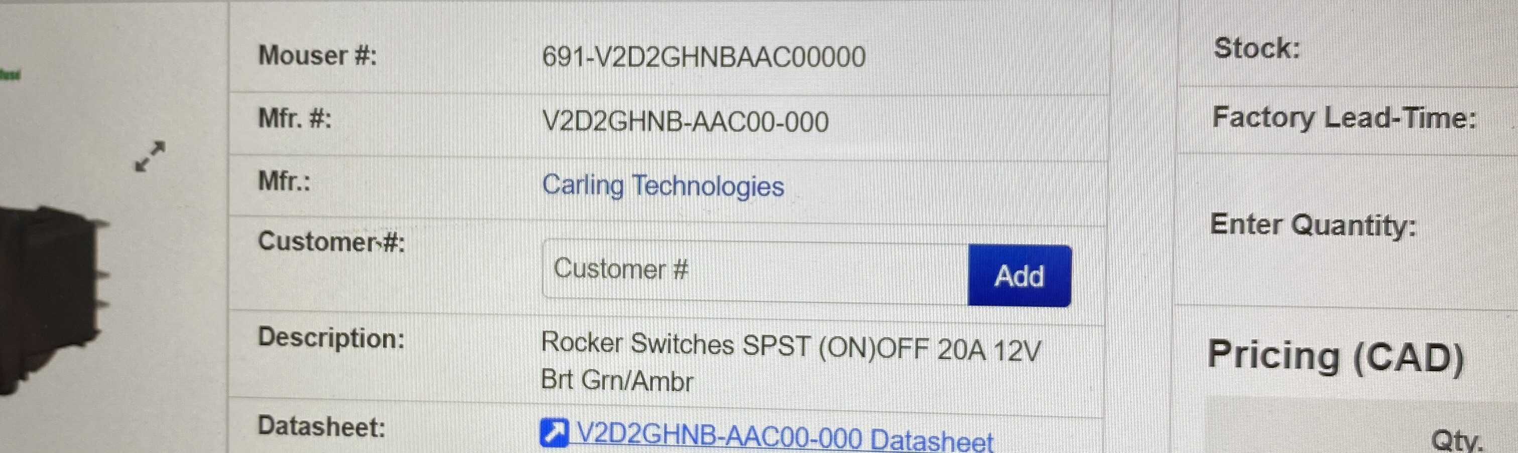
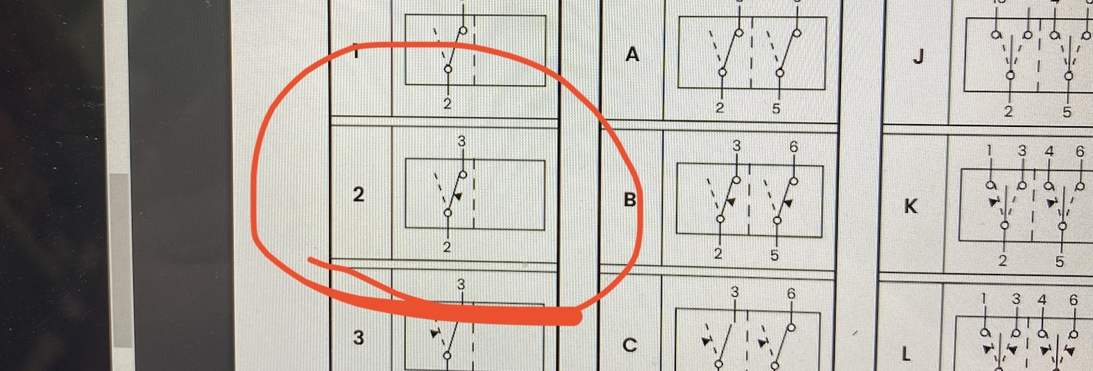
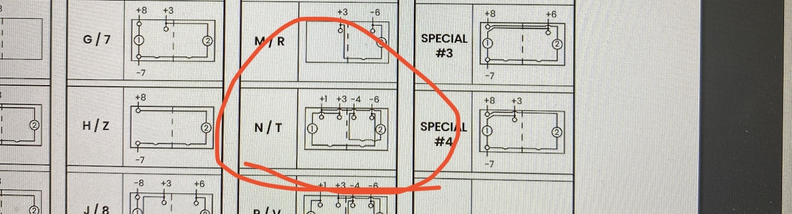
But this is the switch I have in there, and I think these are the circuits. Haven’t studies it to much yet…