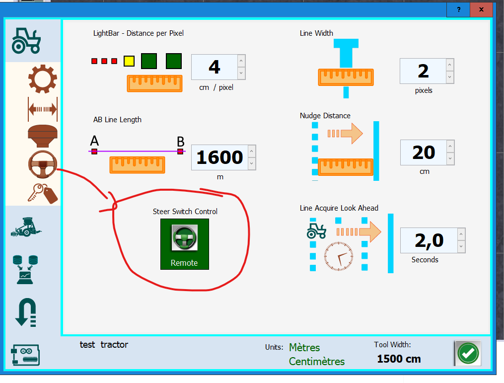
Hey so I’m trying to get a button here to engage/disengage the auto steer, but I’m banging my head against the wall. Which settings need to be set which way? Surely I don’t need to be messing with the ino?
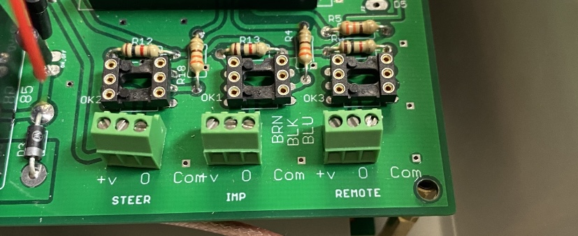
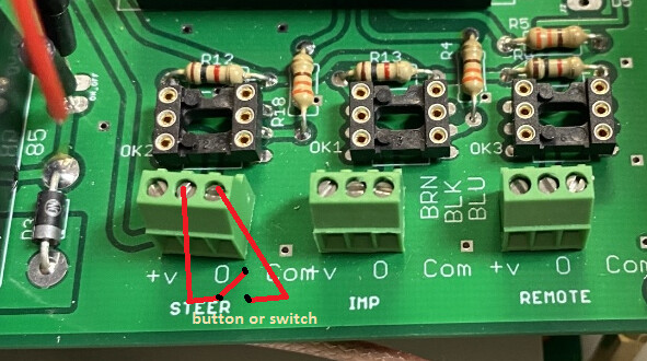
I have it plugged into the two right terminals by the steer spot
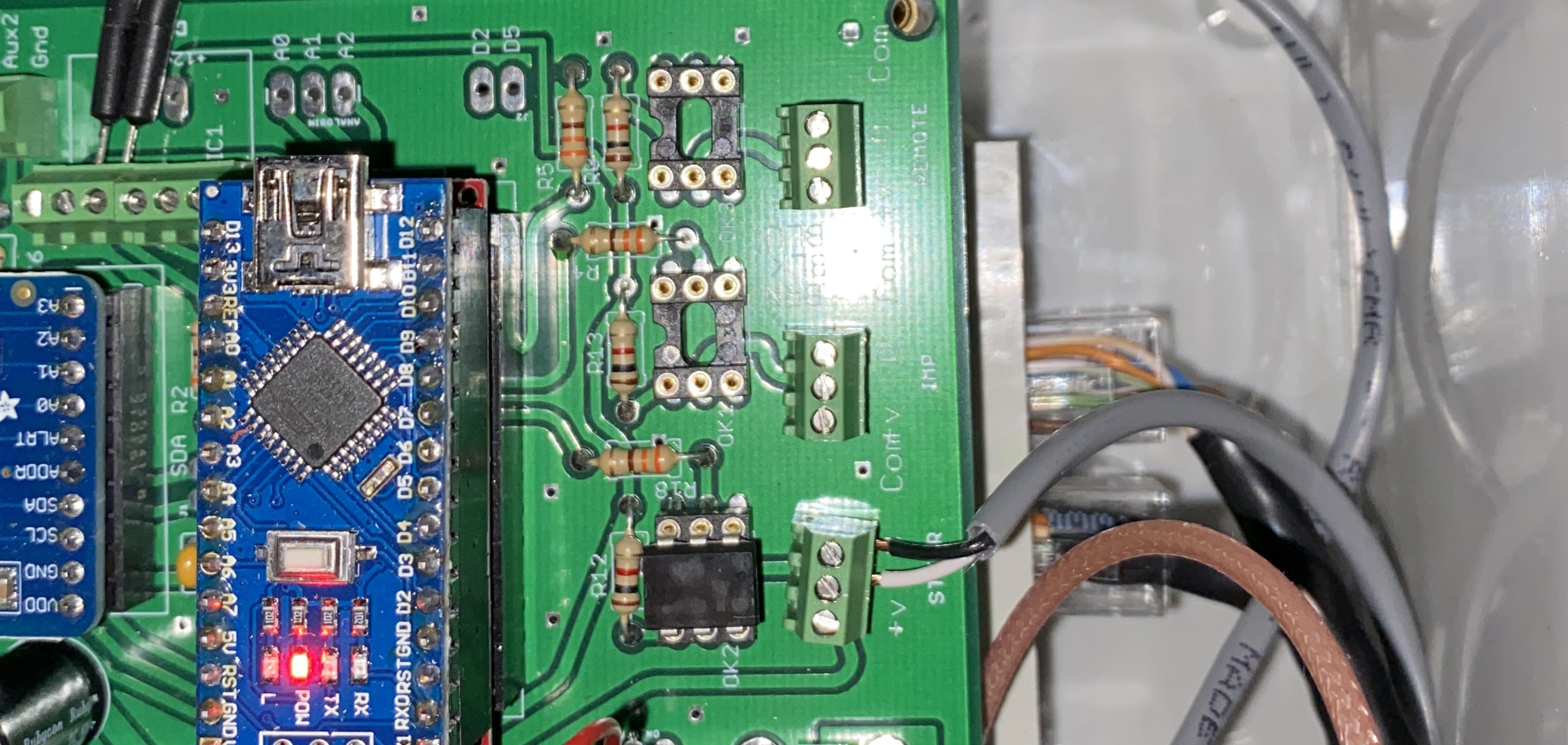
I’ve got it in there, just didn’t have a current picture.
Unless I have it backwards.
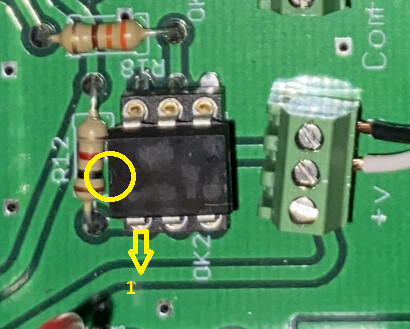
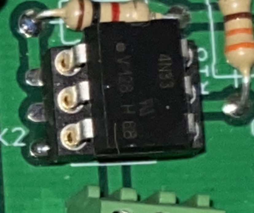
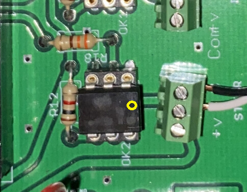
The 4n33 is installed backwards. It might be dead now, but I’d try just reinstalling it correctly and seeing what happens.
DIP sockets and chips always have a notch or a dot to denote orientation. Usually the pcb masking also has a marking. Your socket notch and chip dot don’t match. The socket is installed correctly, the chip should be rotated 180 degrees.
I think that notch you outlined is the DIP socket. I see a dot on the right side of the chip just above the center line.
Regardless of how we interpret the picture, we can agree for OP that the dot or notch in the chip should face away from the screw terminal?
Yes, there is a point, but the notch is above 4n33, the point should not be taken into account (I think)
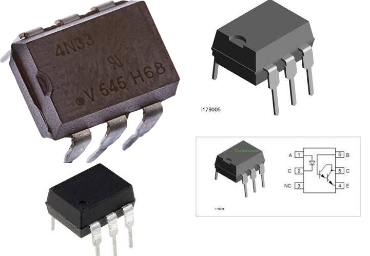
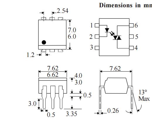
If the IC does not have that notch, it may have a point indicating #1 pin.
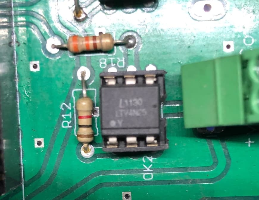
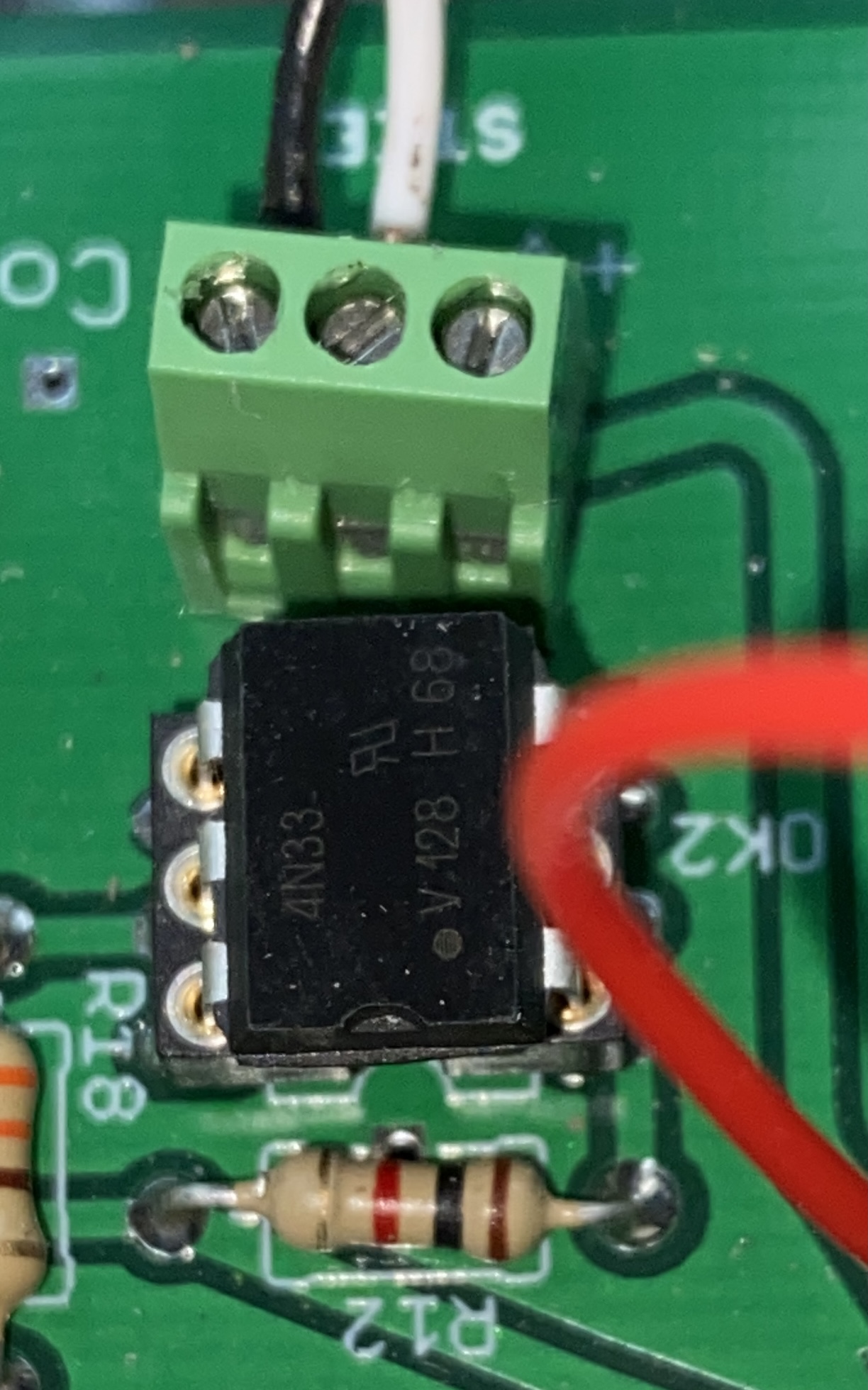
You are right, but I think there is a notch, considering the point you mentioned, the dot is away from pin 1. The 2nd photo is mine, I don’t have a notch, but there is a dot hollow, but pin 1 is not that, although it is a dot.
Looks like your IC is marked like in the attachment, the #1 pin indicator is the other dot. But this IC has a second alignment indicator too (never seen that before).
But here it is important to note that every chip has orientation markings of some kind and the IC orientation on the PCB is essential.
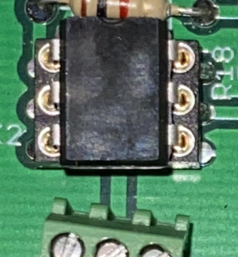
Well I didn’t take very good pics as I wasn’t expecting to look this closely at them but…
1 Like
I guess I’ll take a closer look this evening. I just assumed the the little notch matched the socket. Didn’t look twice.
Still not getting anything
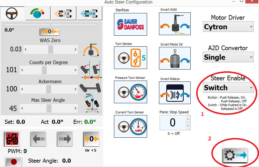
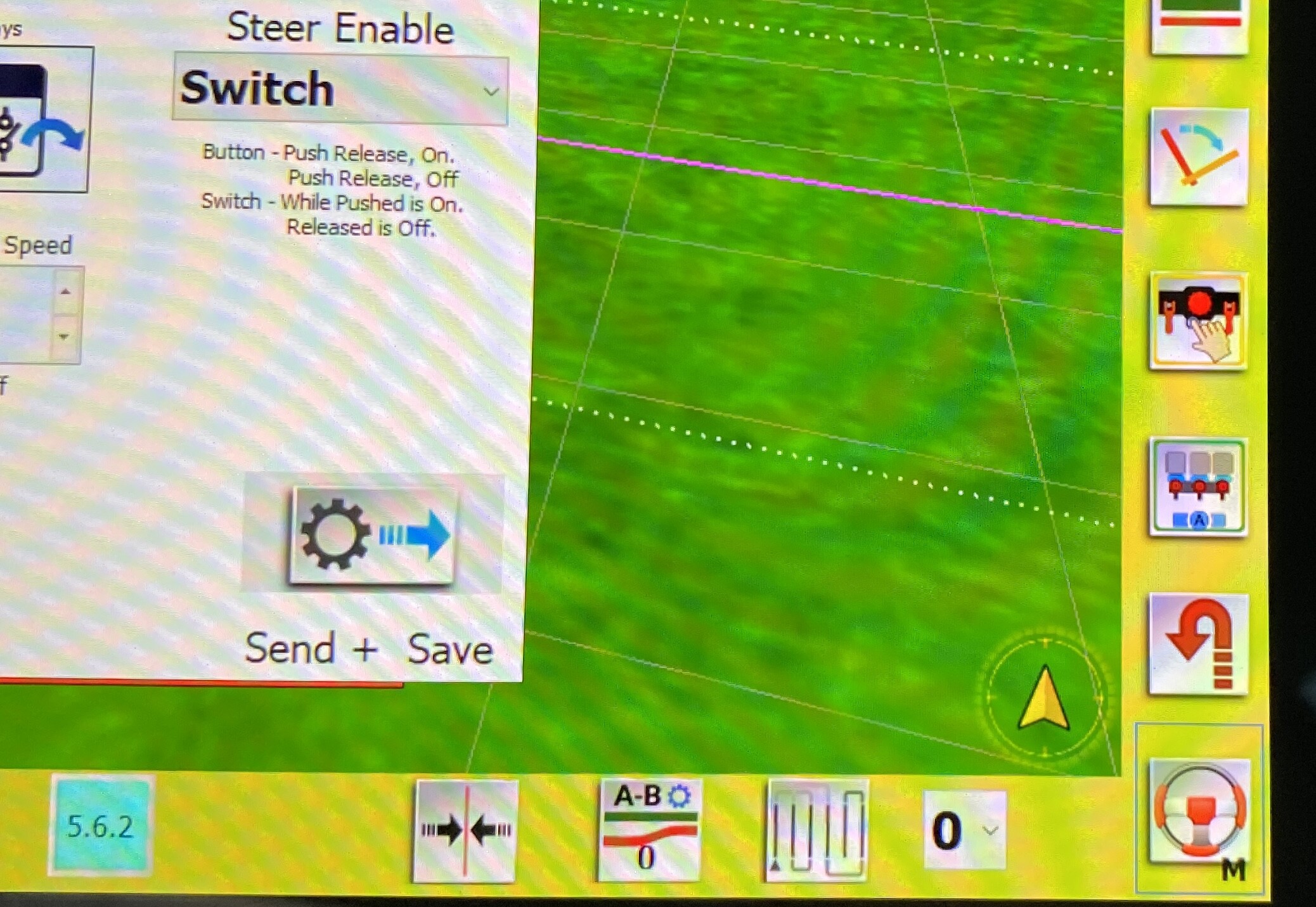
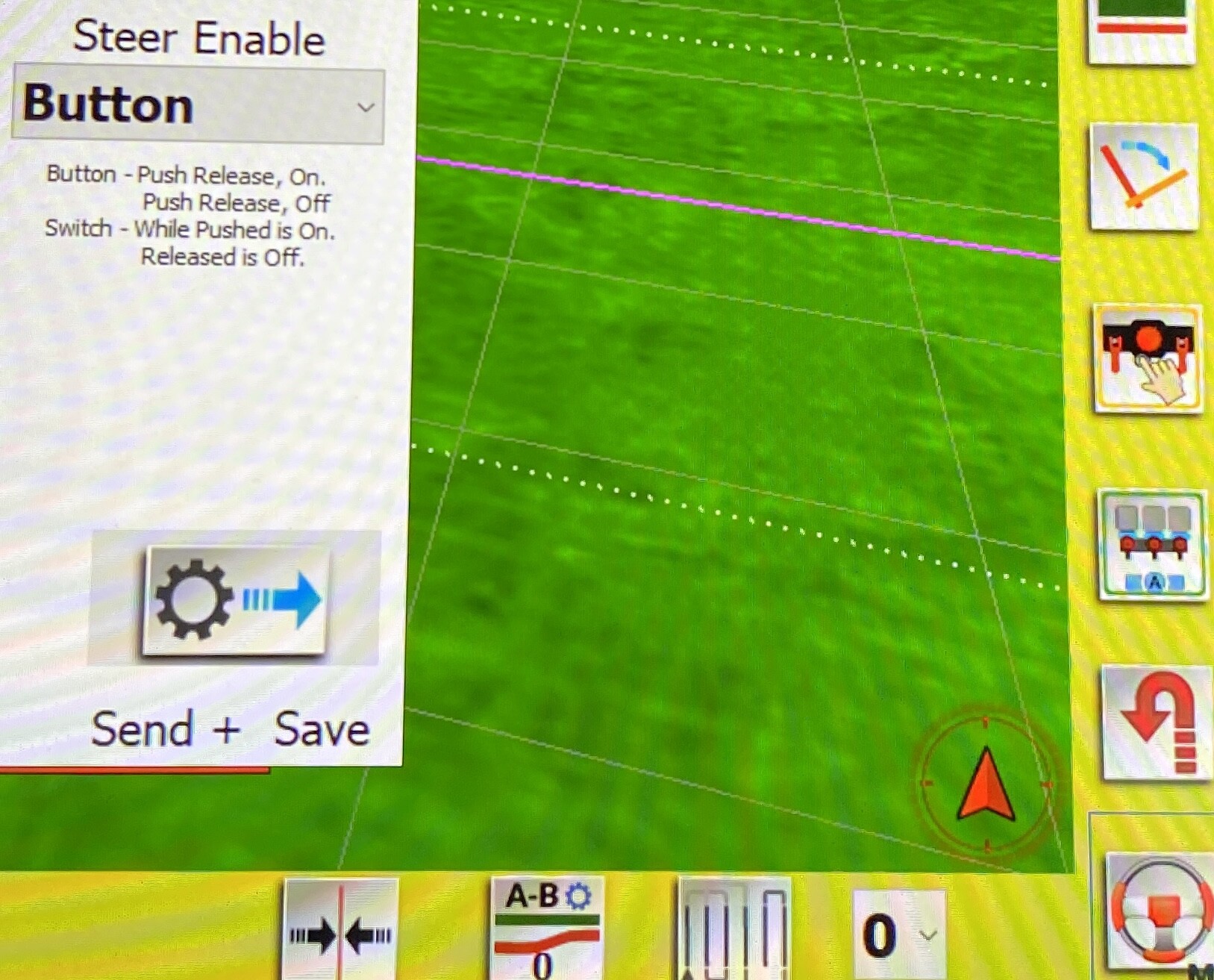
If I set it to switch, the compass indicator turns yellow. Set it to button and it turns back to red. And if I hold the button while in switch mode, it doesn’t do anything.
1 Like
you are in manual mode so you need to activate the autosteer button on the screen
switch mode the compass is yellow because waiting the activation on the screen
button mode the compass is red for same reason
for switch or button you can activate the remote to avoid that
The nano need a full cycle to see what you have done. So push AND release, then you see the correct reaction of the Switch situation.
Ok, so…
By holding the button down (holding the contacts closed) while in switch mode, I was trying to simulate a switch.
I’ve been trying that remote button a lot to no avail.
Although I did just swap out my optocoupler, and I’m not sure if I played with that remote button after that.
Remember that in AOG language, the button stay down and keep connection after you remove finger. And switch only connect momentarily.
So choose the type in settings, that match the one you use.
Edit: You must drive faster than minimum speed, else AOG cuts autosteer off again.
I’m pretty certain your optocoupler was correct. Just checked a bare board and the notch is toward R12.
Am I being completely daft here, or shouldn’t you be using + / - for a switch?