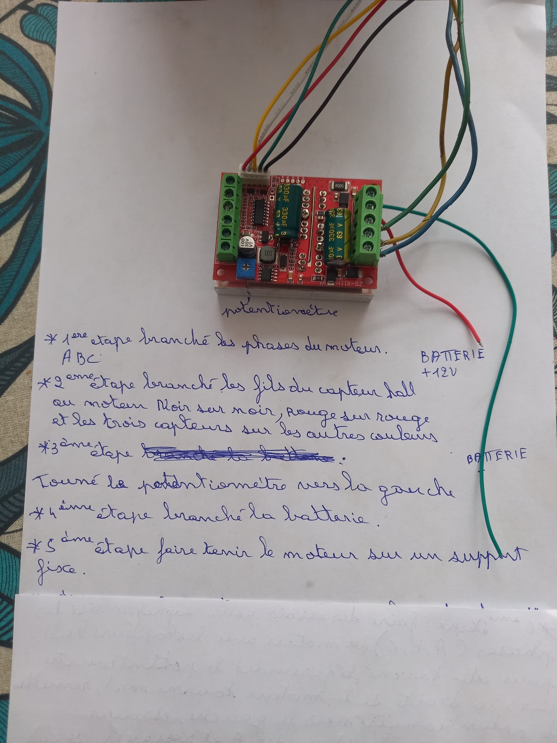
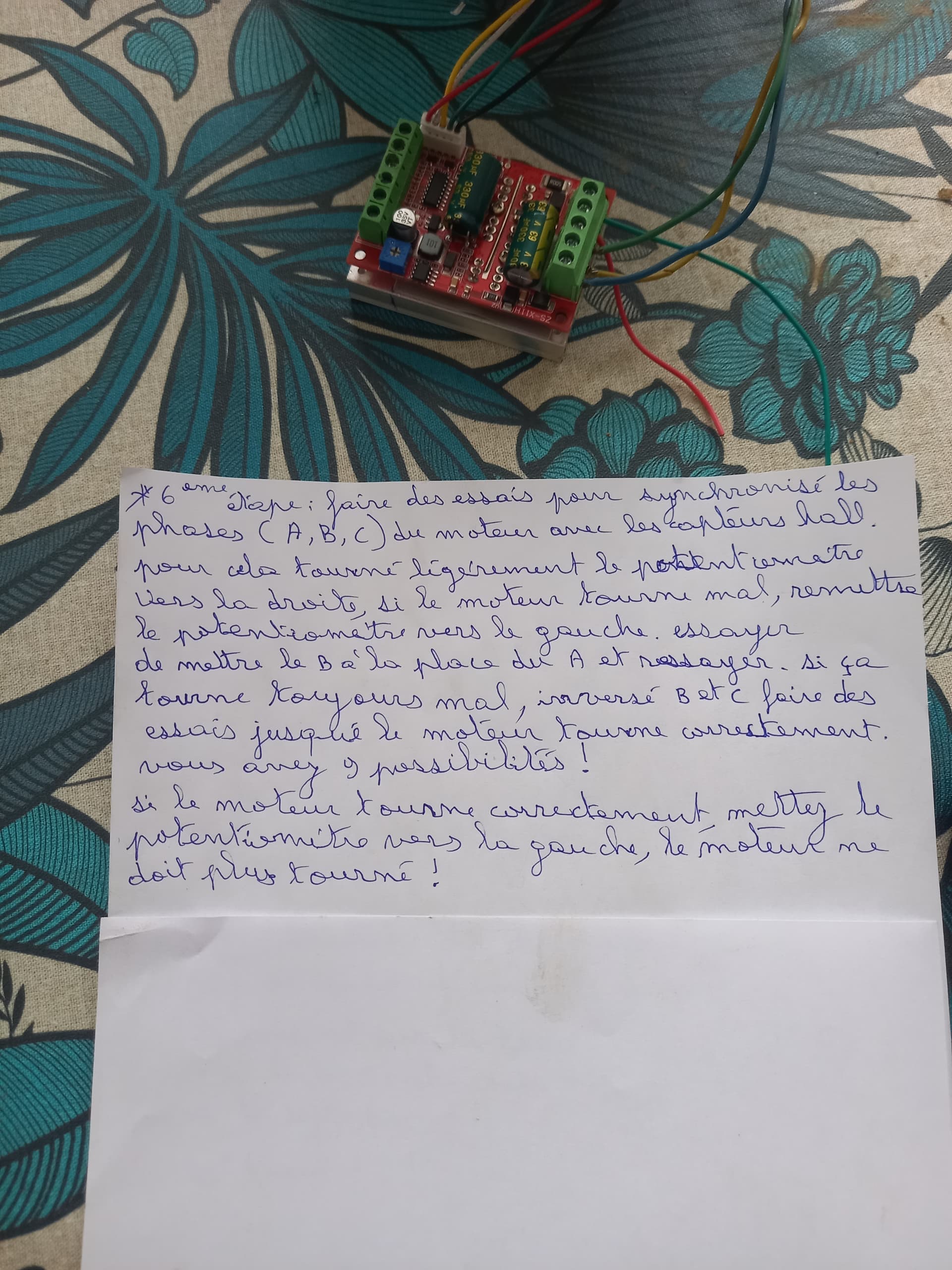
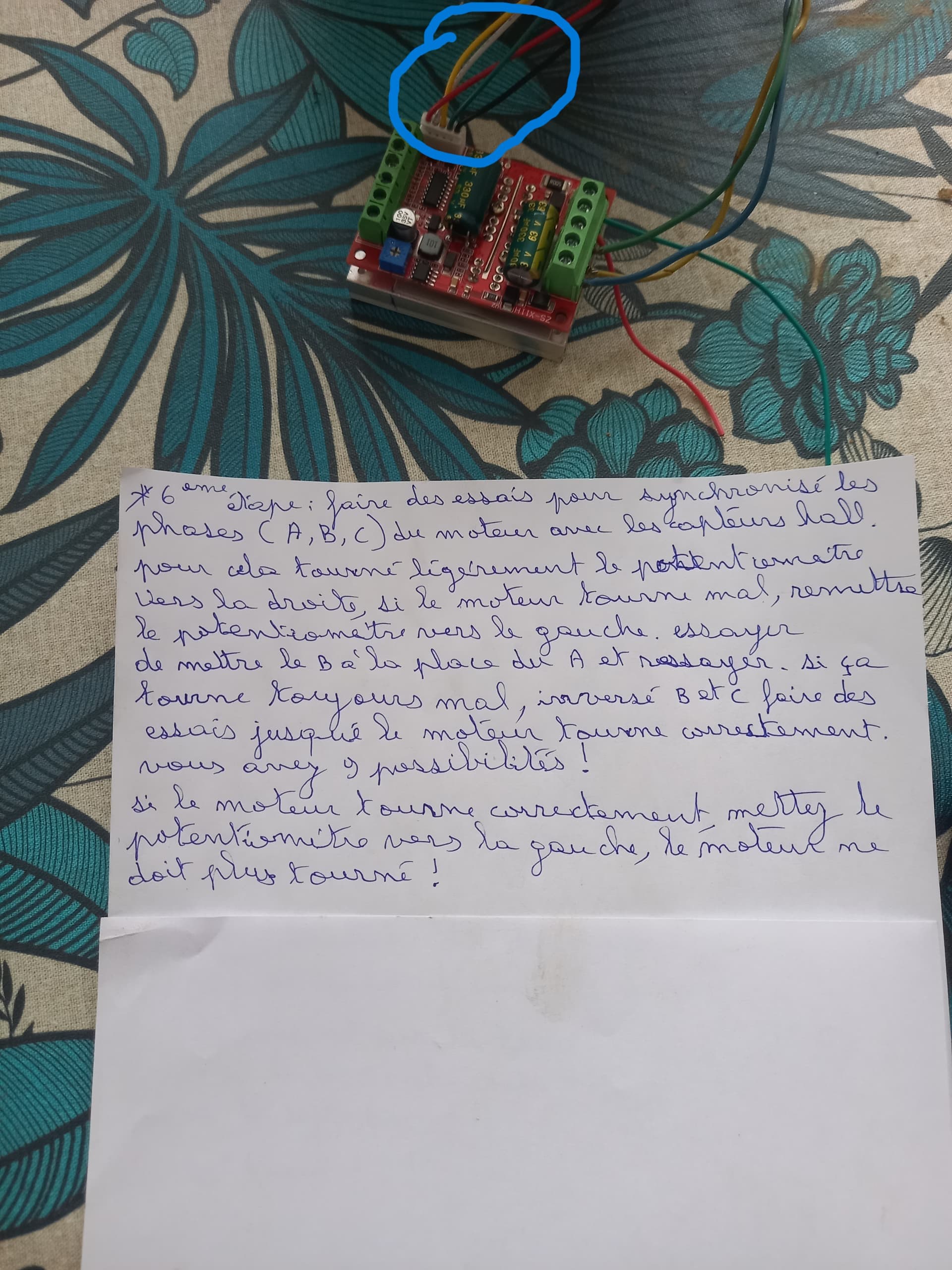
Il y a 5 fils pour le capteur hall, il faut branché le 5 volt sur le fil rouge et gnd sur le noir, les autres au hasard, il faut faire des essais pour synchronisé les phases a, b,c avec les capteurs hall
Do you know if it is possible to simply connect only 3 phases without a sensor?
Non je ne sais pas peut etre un esc mais je n’ai jamais essayer
Hi everyone!
with patience and thanks to the help of this forum I managed to make “my” minimal system work!!!
In summary:
HP i5 tablets
C099-F9P
ArduinoNano
ADS1115
CMPS14
W.A.S. 1K potentiometer
ZS-X11H (motor driver)
Hoverboard wheel/motor.
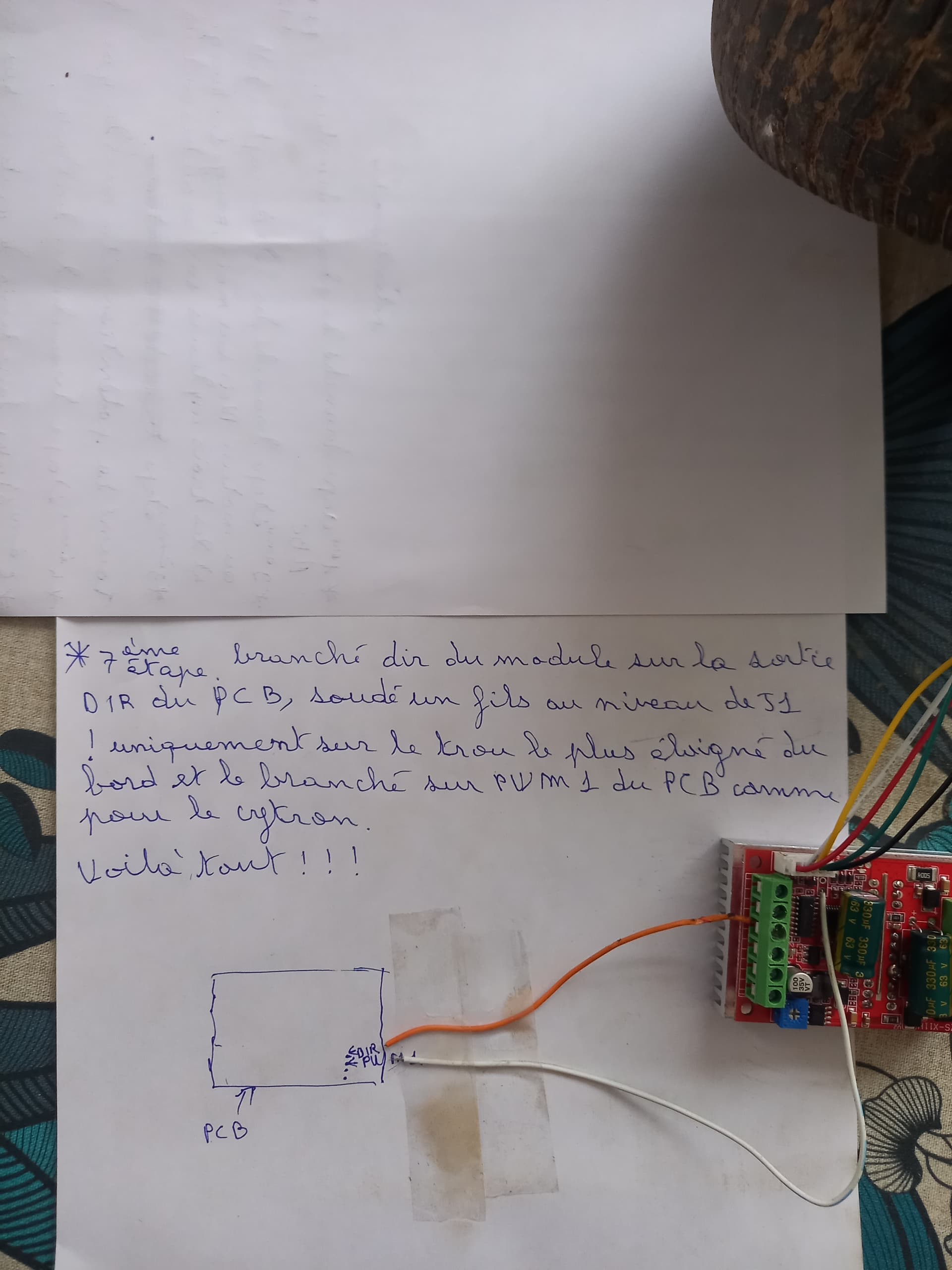
I connected as per the schematic found on the old PCB-V2 AutoSteerShematic.pdf on SupportFiles.zip.
The connections are direct without resistors and capacitors, powered directly by the Arduino Nano’s USB.
The motor driver powered with 12Volt.

I notice in your video that on the uturn your motor spins the whole time, just keeps trying to turn harder to the right. Your steering wheel would have reached its limit very early in the turn. Do you think that’s just a settings problem in the simulator? Or will it be an issue when you put it into service?
the motor turns randomly because it is not mechanically connected to the W.A.S., if I move the potentiometer (WAS) it changes direction immediately, here on the bench it cannot be realistic in simulation. What is important for me is the gradual operation, the silence and the excellent torque of the motor/wheel for steering.
Hi. How you measured that torque enough?
I measured the “strength” of the hoverboard motor by braking with my hands… I think it is more than enough to control a steering wheel with orbitol…
hi screasan
I helped my farmer friend set up AGOPENGPS to work on a jd combine 9650. Same set up as your bench testing but added a relay between the DIR from the micro all in one board and the DIR input on the brushless motor controller. We found most of the hover board motors were 24v or 36v. I think both versions worked ok. The setup he has working is using a 36V motor with 32V input.
The farmer did all the hard work to attach to the steering wheel and spline. All the wires from the motor need re routing and some lathe work required to make it all fit. He designed parts to capture the bearings and all 3d printed. These parts are used to attach the original steering wheel. He has used the setup for two seasons ok.