Just wanted to share my experience with AOG in my Steer Ready NH T8050 using the 4.5 Micro PCB. I also am hoping this info will help others that are trying to integrated with the New Holland or Case tractors that have the factory auto steer with the 40 pin connector that is not steered with canbus. It took awhile to cross reference diagrams and compare to other 40 pin tractor users that have posted on here. Two primary people to thank is @Larsvest New Holland and @FiveFinnishFarmers Case with there own information as they were crucial to figure out what I have. Make sure to check out there own posts regarding there 40 pin tractor installation for information as well. Anyone following this that doesn’t have this particular tractor should consider getting the factory service manual to look at your own diagrams to make sure things match up. I found a digital version for mine at a decent price and was very helpful. It also gave me peace of mind that I wasn’t going to break anything when hooking it up.
First off the here is a diagram of the harness I made that I used to connect the 23 pin to the 40 pin connector.
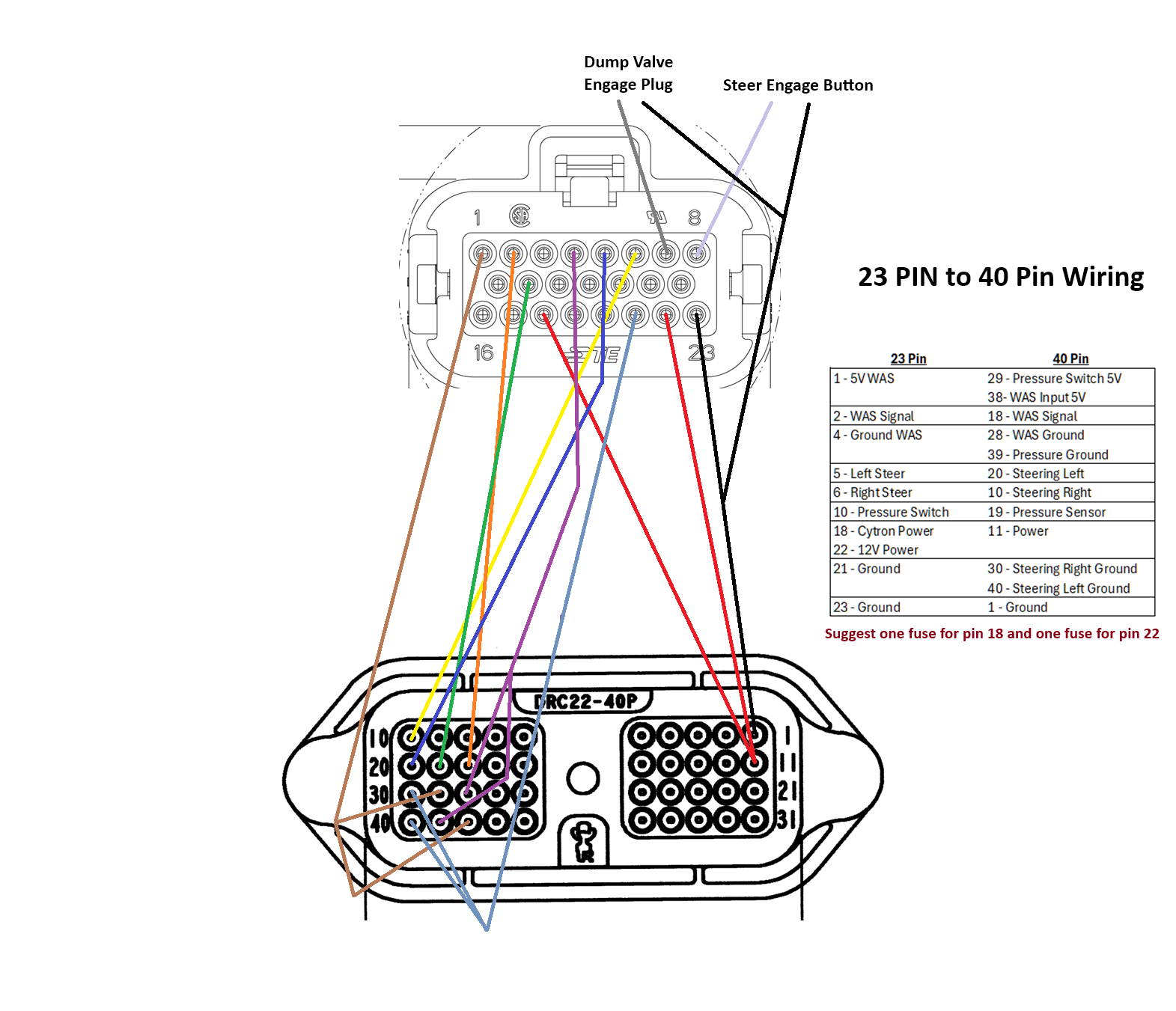
I used pin 18 to power the Cytron. I mainly did this to make it easier for the PCB can be swapped to a different tractor easily. You don’t need to do this but it is why I choose to go that route.
Also I noted that a fuse for both Pin 18 and Pin 22 should be in place but I only put one in for pin 18 and just relied on the board fuse to take care of pin 22. There is a fuse in the tractor for the autosteer circuit as well so I feel ok with this decision. Do what you wish but I am just suggesting it.
There are a few pins that don’t show up in the harness that I had to find a way to get them from somewhere else.
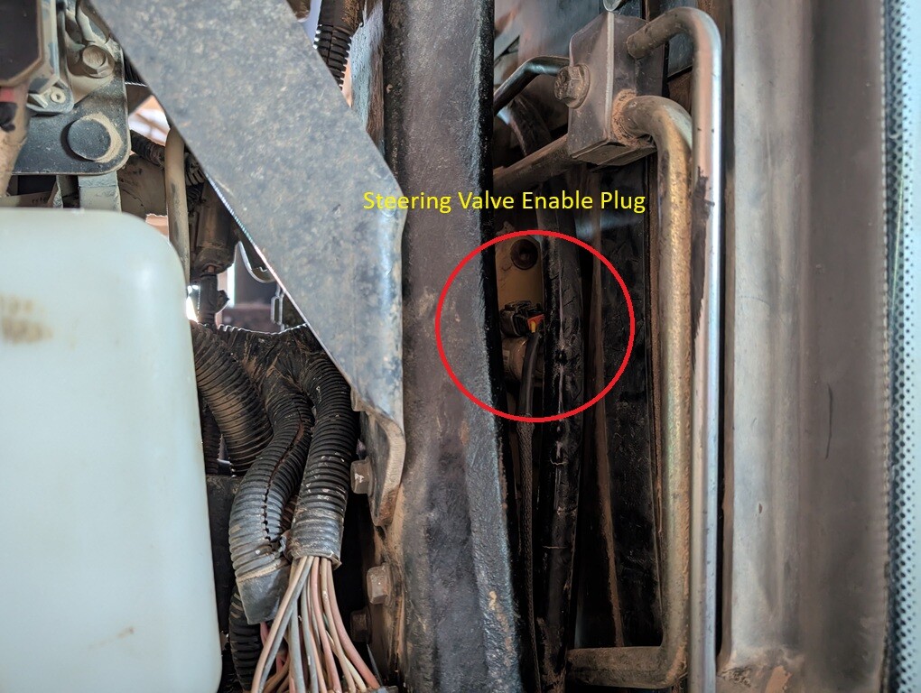
Autosteer Valve Engage - On the T8050 this pin ends up at the transmission computer under the back window on the outside of the tractor and is under a cover. I could have tried to pull this pin but I ended up not doing this. There is also no other connection points along the factory run where I could steel a pin either. I found an installation guide for another very large auto steer company that just bypassed this completely by running there own wire all the way to the steering block and I did this myself. I know others have found other places to get this pin on different versions of there own harnesses but this worked better for me. This is using a 2 pin Deutsche DT06-2S-P012. I just removed the old two pin connector and plugged in my own.
Connector Location is door side between engine and firewall.

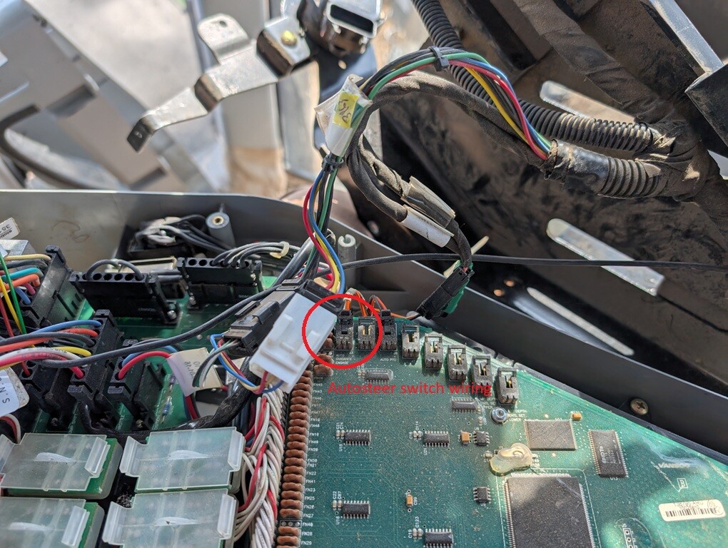
Autosteer Switch - There is a factory autosteer button. However it looks like the clean way to access it is off the CAN bus. Instead of trying to figure that out I instead just took apart the armrest and decided to just cut and splice the plug on that. Unfortunately the manual didn’t give me any info on what plug it needed or I would have elected to use the factory plug again. This maybe different on others if a button like this is installed. A separate button can also be made and bypass it all together but I know some just like to use the factory button.
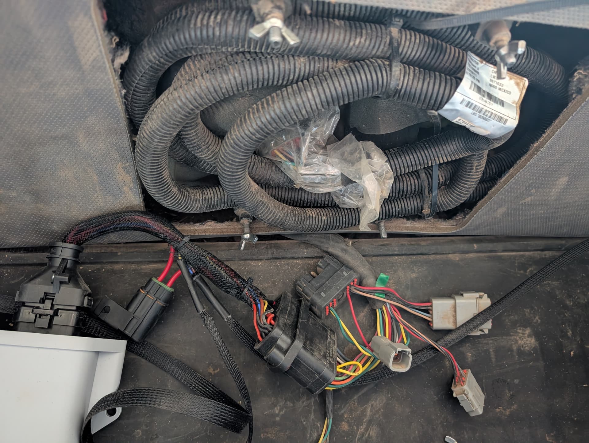
This isn’t fully installed as I tucked the 40 pin connector under the trim and hid it in the cavity. Only regret is I wish I made the cable much longer. It got it to work but would have been way nicer if I had more cable to work with.
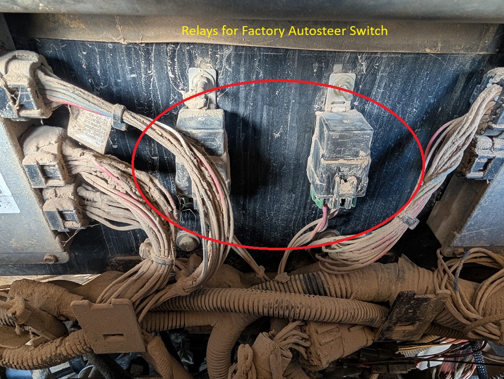
Also this tractor does have a factory autosteer disable switch on the fender. If this is turned off it does not disable the power to the AOG PCB. I thought it would but it only disables the hydraulic valve’s left and right function using two relays. I have the location shown bellow. I actually had to do some troubleshooting originally so I needed to find them to test them. On this tractor they are outside under the cover in the back but on others they could be in a number of places.
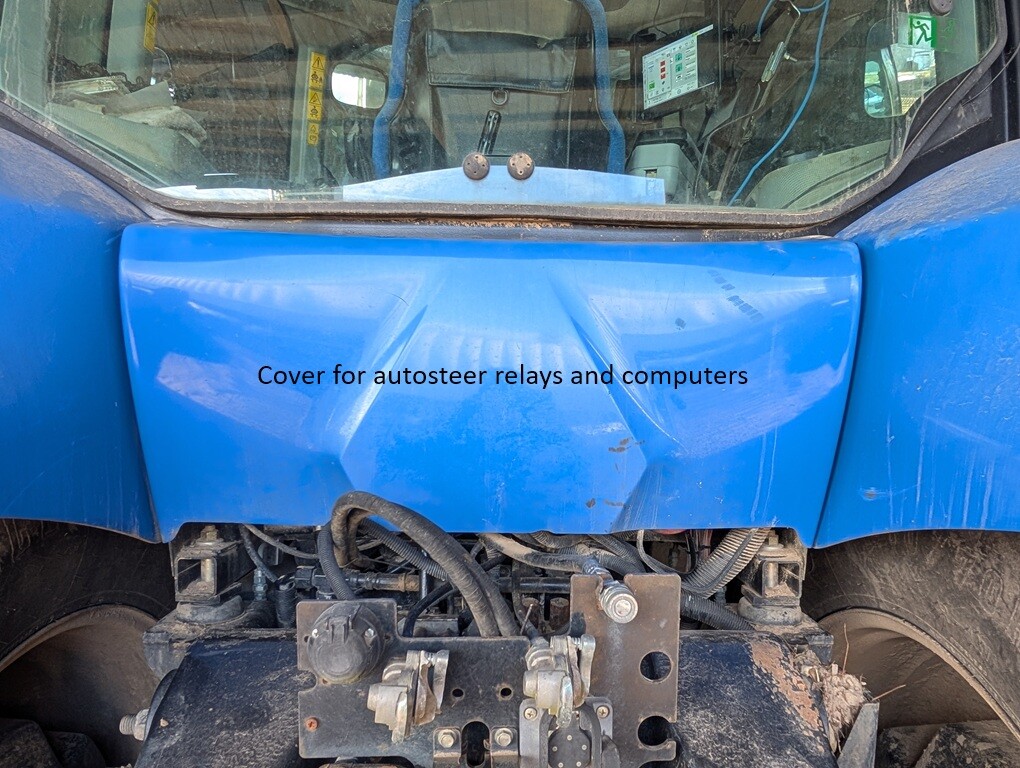
One thing that I might change is to add in a relay to turn on and off the PCB when not in use since pin 1 isn’t switched but it does turn off with the key. There is also a pin on a separate plug in the same area as the 40 pin connector that is wired to the on off switch on the fender that could turn on and off a relay that could break the power.
The WAS on this is different from others that I have looked at and is pretty straight forward on this tractor. The WAS is shared with the autosteer and auto diff lock however they are completely separated from each other. So there is 6 pins total on this WAS plug.
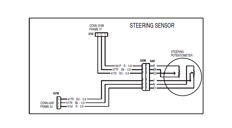
For your own WAS it maybe really different wiring from mine. This is where I would look at your own steering sensor wiring in your manual to understand how yours works. The other two users that I worked off of had different WAS setups that shared with the auto diff lock and may or may not have to have a some wiring done in the front. FiveFinnishFarmers had to change some of his wiring in the front of his tractor to get his to work properly as an example.
40 Pin shopping list if anyone is interested…
40 Pin Plug DRC22-40PA
Pins for Plug 1060-20-0122 I actually ordered the wrong one initially but this is the right one
If my pics break at some point here is files of pictures and wiring diagrams uploaded.
Overall it works pretty good. The only real complaint I have is that tuning this has been kind of a headache for me at least. I have to set the min to move up really high for the steering to even try to move. Right now I have it set at 82. With it that high small adjustments with proportional gain feel kind of large and I have been playing around with the max limit as well. Since this tractor is only used for tillage and ground ride changes a lot it moves away off the line a lot but not by too much so I am pretty happy with it.