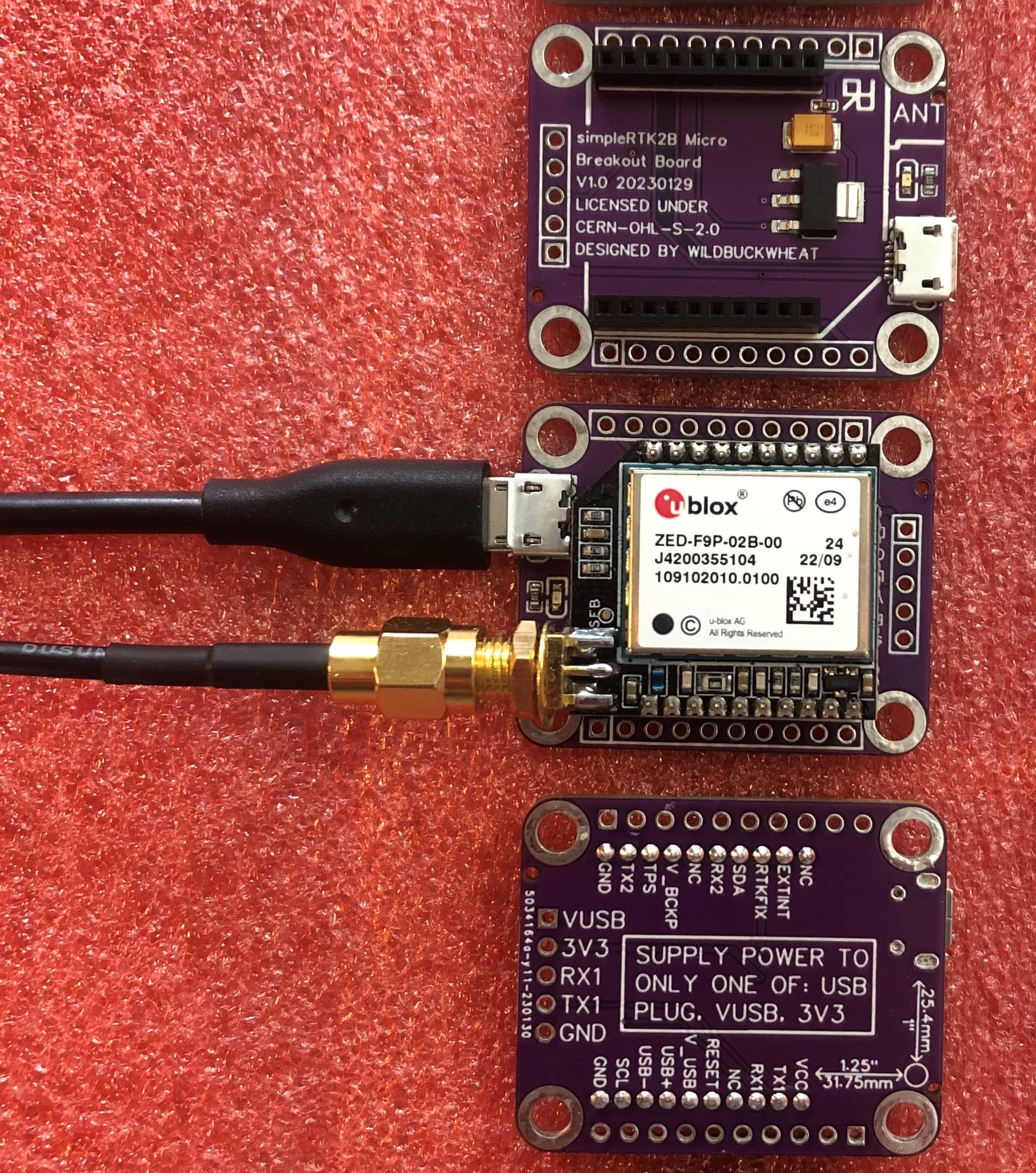
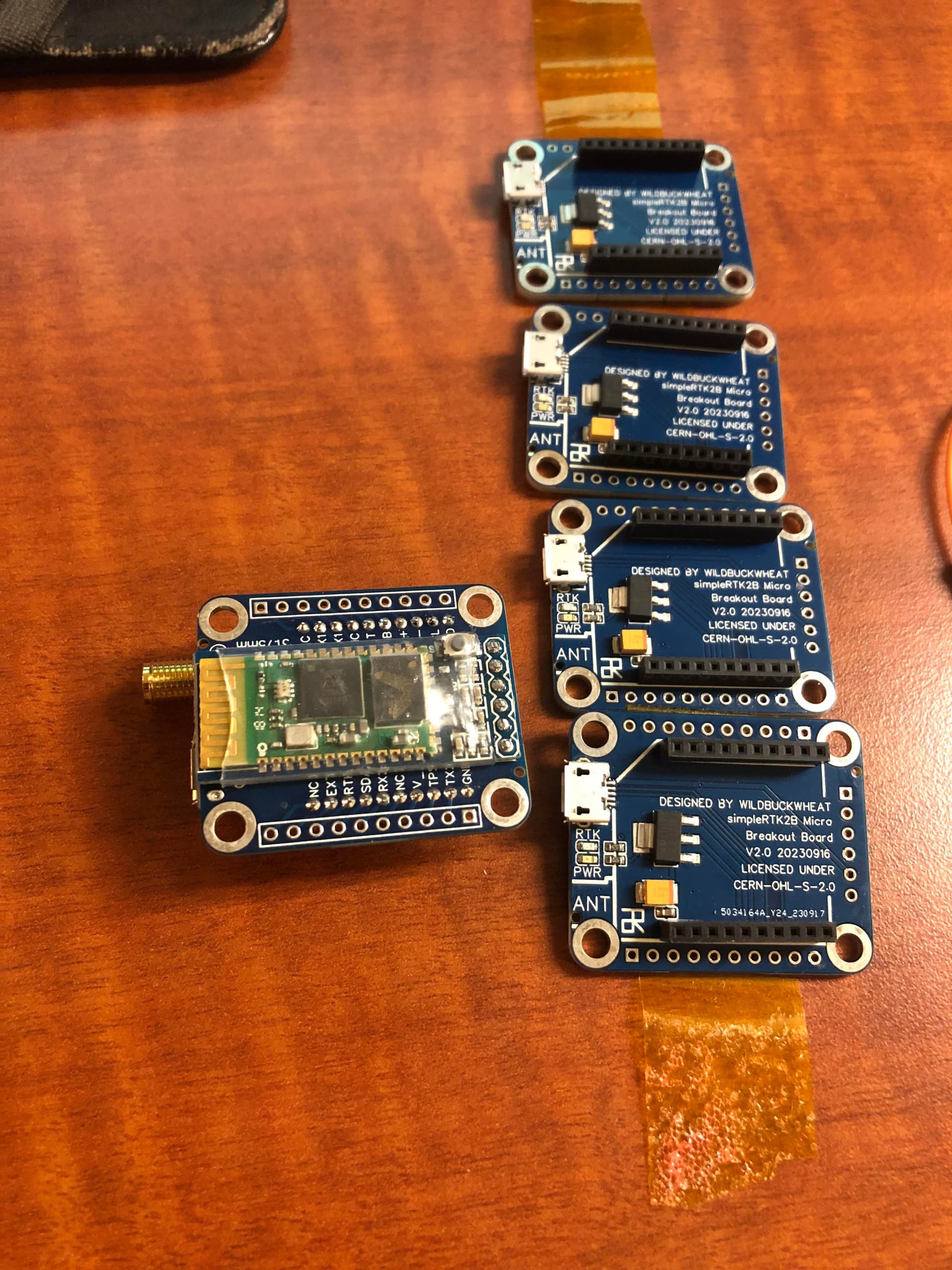
It’s a small board with a USB port, you can use it with a raspberry Pi, Orange Pi, Banana Pi, Windows, whatever has a USB port.
All of the Micro F9P pins are broken out to 0.1" spaced pads, so if you want to you can add headers and use the board on a breadboard, connect to the hardware serial, power it externally, etc.
You can purchase the board fully assembled from JLCPCB using their SMT service.
All the files are here:
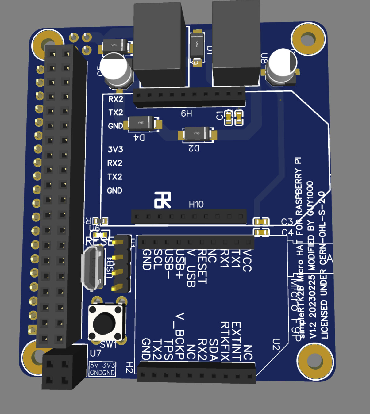
Next is the simpleRTK2B-Micro-Hat-for-Raspi.
This board connects the Micro F9P’s UART1 to the Pi’s UART 1. There’s no USB cable required for normal operation if you setup your software for UART.
A USB port is included in case you want to program the Micro F9P using U-Center.
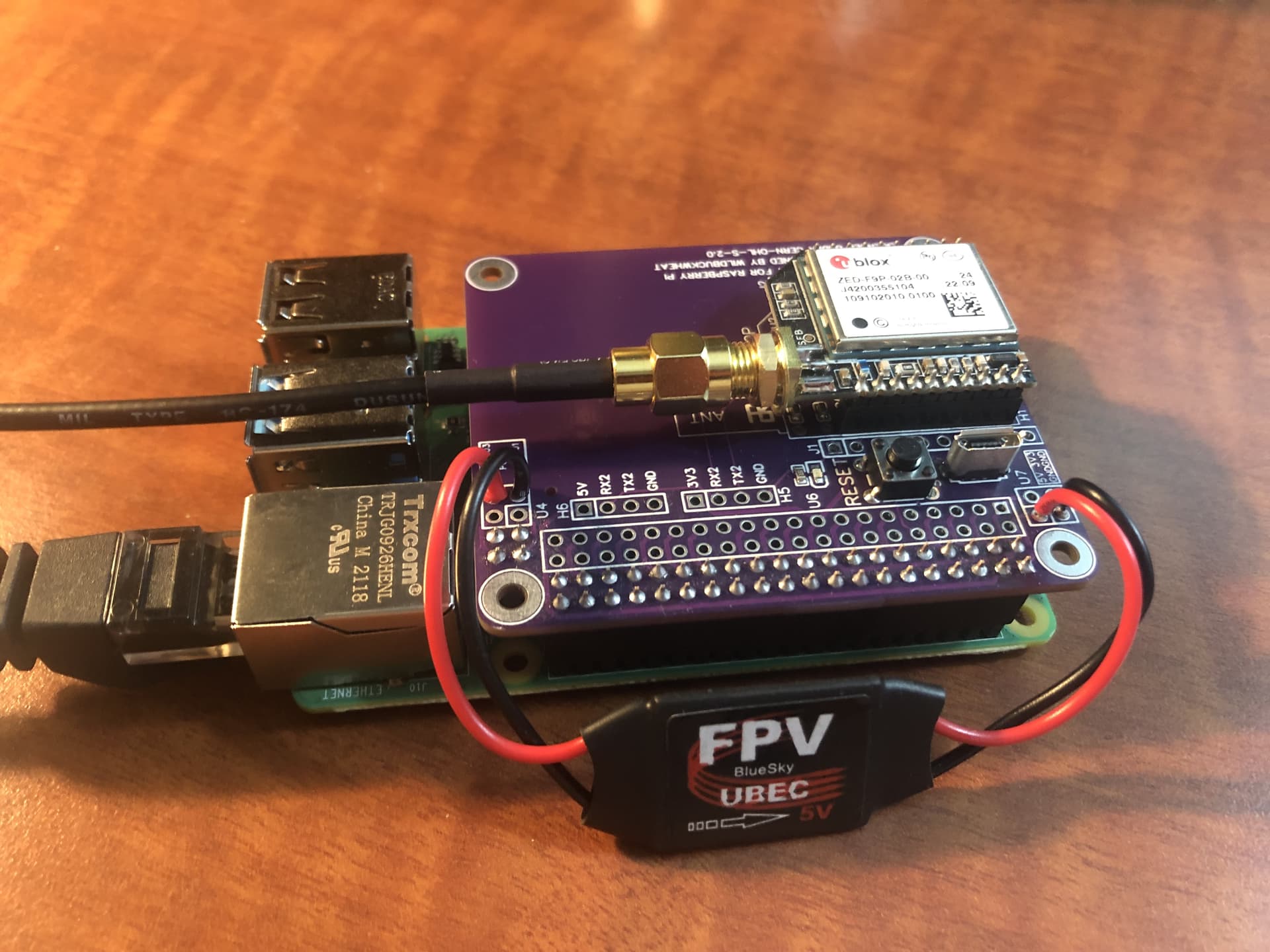
All of the Micro F9P pins are broken out to 0.1" spaced pads, and the Pi’s 40 pin header is duplicated as well. You can experiment with I2C OLED screens, adding switches, etc.
Or experiment with PoE, passive PoE is very easy to add with a voltage regulator. I added PoE to mine, but of course you can also power the Pi over USB like normal.
You can buy the board almost fully assembled from JLCPCB. You’ll have to source and solder the 40 pin header that mates with the Pi yourself.
Do you normally use a POE adapter? or can you get 802.3af power right off the Pi?
Not sure how many UARTs are easily available on the standard Pi header, but if a board could supply 1 amp, would be nice to have an xbee slot on the hat for a radio transmitter as well.
I’ve always liked the idea of using RC power regulators. Good reliable power in my experience.
The Pi3B+ and Pi4B break out the 4 “unused” ethernet wires to a 4 pin header. I just connected a UBEC between those pins and the 5v rail.
There’s only one good Pi UART. There’s some software uarts I think, I havn’t played with those.
The Micro F9P has 2 UARTs, the xbee could be connected to the second UART. I don’t know if there is quite enough room on the board for an xbee or if its ok to mount an xbee so close to the F9P. I did break out that second UART to 4 pin headers for an external radio if someone wanted to connect a radio with wires.
With RTKBase you can also use a RTCM serial service, so you could plug a radio into the Pi’s USB port and send messages to the radio that way.
Very good. I’m sure any Pi clone would have to be checked to determine if that’s the same.
I’ve also been buying 802.3af power adapters that split out to USB power micro or mini connectors. They are pretty cheap on AliExpress and work pretty well. I think they can supply an amp. Not sure how much power the Pi’s 3.3v regulator can supply, so still a good idea to power the hat through some kind of external regulator, even if it is from the same 5V supply.
But you’re talking about passive POE here.
Yes USB works fine, although the latest USB to xbee adapter I bought only can supply 300 mA, so it’s not enough to run a 1 watt base station, but I think I can bodge a bigger regulator onto it.
Very good work on this board. I may have to order one. I’d like to setup a complete backup base station that’s ready to plug in and go should anything happen to my active one. Need a bit of redundancy should something happen to me leaving everyone else in the lurch.
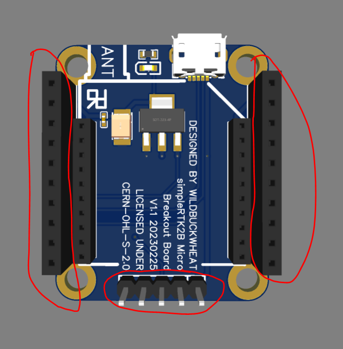
It should be safe to continue past that warning. Those parts exist in the schematic but are intentionally left off the BOM. They are just there to put pads in the right place and then you can solder in headers if you ever want to. Just make sure that the JLC preview contains the 2 F9P headers and other parts and then you should be good.
If you want to wait a little longer I’ve made an updated version. Its being made right now and once I’ve tested it I will release it. The size of the breakout board coincidentally happened to be perfect to fit a ~$4 HC05/HC06 bluetooth module to the back, but the pinout order on the breakout board was incorrect to do that. The new design is basically the same, but those 5 pads opposite the USB connector become 6 pads in a different order.
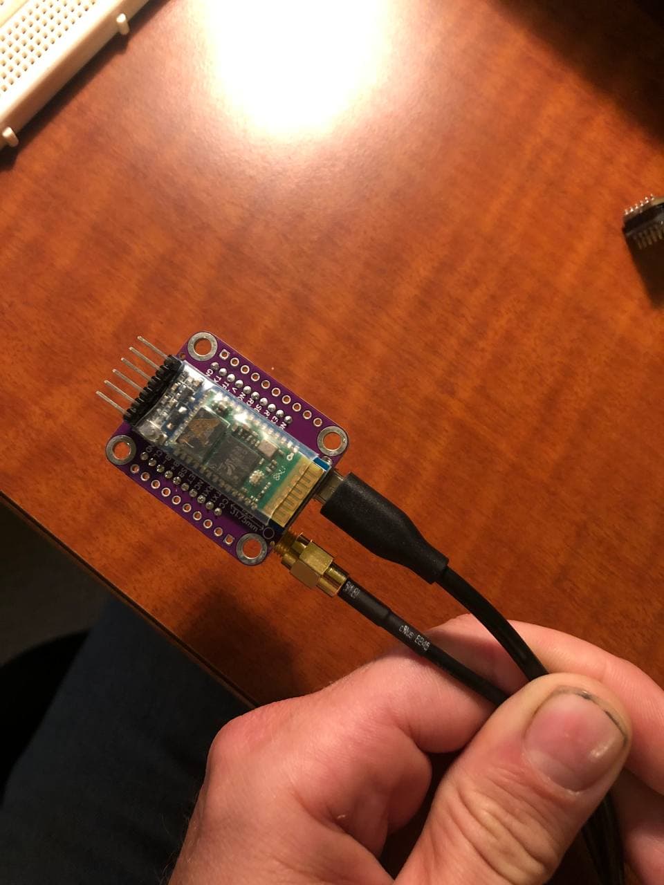
Here’s such a bluetooth module held up to a breakout board. I’ve tested it with jumper wires and the range was about ~30’ outdoors. It should be slick to use with a USB battery bank to map field boundaries on the ATV. I’m 3d printing an enclosure to hold all those bits together right now.
You probably could, but to fit on the board it would have to be double sided SMD and that double sided assembly fee is hefty. This was more of an engineering by inventory thing and the change needed was so small that it felt like a missed opportunity.
EDIT: The HC05 modules are pretty outdated too, and have never been supported by iPhone. If assembling with SMD then a BLE version would probably be better.
Awesome.
Thanks for the swift reply. I have decided to wait for the release of your new design. Easier connection to a bluetooth module sounds fantastic.
Recieved my order of 5 modules in the mail this week.
The module worked great! Thank you so much for sharing the design.
Your use of micro F9P’s usb connection made the setup of RTKbase very simple. I struggled with identifiying the correct COM port on my pi when using the USB-XBEE adapter, and in the end I gave up and ordered your design. Using the detect/configure option in RTKbase, similar to the standard F9P, worked flawlessly.
I am waiting for HC05 in the mail, and will probably ask for help or report back when they arrive.
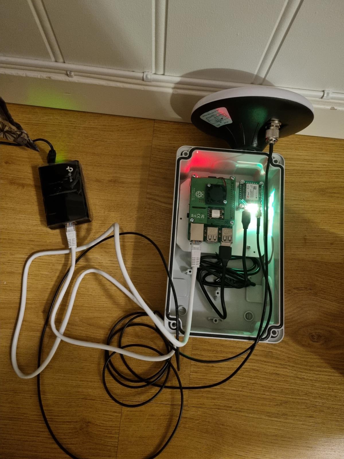
Attaching a picture of the base station setup I am attempting to finish.
Raspberry Pi 3B with PoE-hat.
Micro F9P with your connector.
Budget survey antenna.
TP Link PoE injector, TL-POE150S V3.
Plastic ice scraper as a “mounting hole adapter” in the connection box.
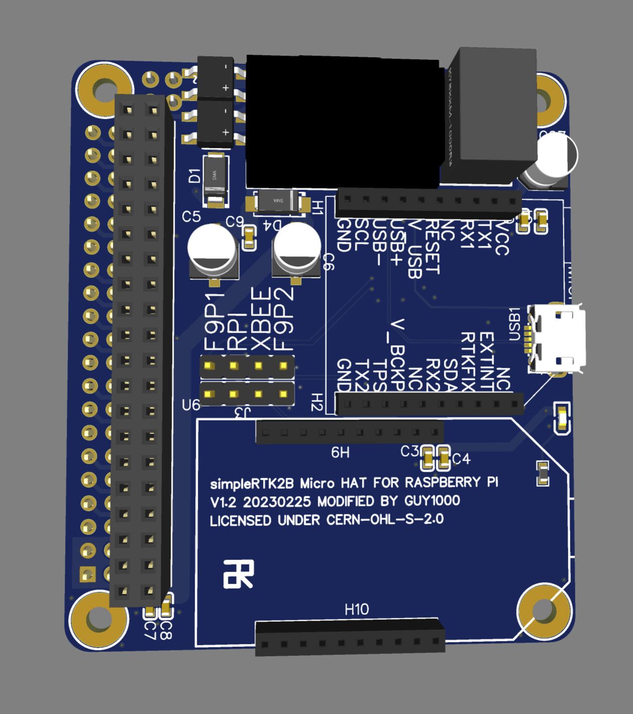
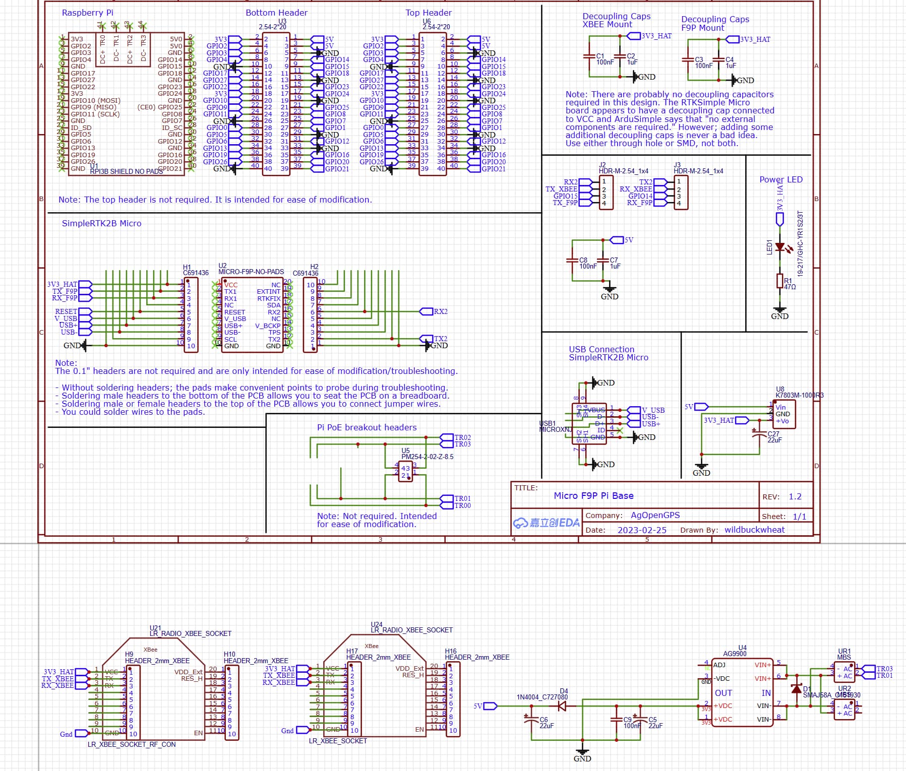
First draft to add a XBee socket to the raspberry pi board. I also included onboard POE regulators and a 3.3v regulator to power the F9P and XBee separately from the raspberry pi power supply. Still have to make quite a few changes though.
Cool project Guy1000. I’ve got a similar project half finished too. It uses a PoE module like a Silvertel, for proper PoE hand shaking. Mine doesn’t fit inside the Pi footprint anymore though.
You can probably lose the push button, I’ve never used it. The USB port could be a horizontal one underneath the F9P if you want to save some space too.
I took your advice and made some changes. Was just able to squeeze a silvertel AG9905 in there for POE. Also added headers to select which serial port is connected to which, it also allows the F9P to be easily connected via usb and leave the serial port for the XBee. I think it looks a lot better now, unless anyone has any more ideas I will probably straighten out a thing or two and order a test batch. Any advise or ideas is appreciated. Apologies for the butchered schematic
It looks great, are you addicted to PCB design yet?
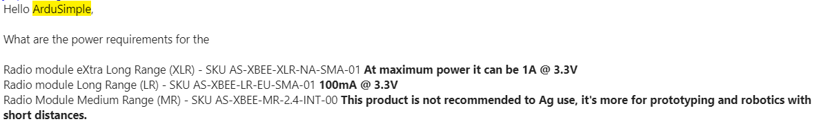
I am not sure if the Silvertel’s 9905 1.8 amp output current rating is sufficient to power everything. I’d wager that 1.8a is probably ok for a Pi 3b+ and the F9P alone, but that Ardusimple XLR is quite a current hog.
The 7803 is a switching voltage regulator, but if only feeding in 5v then you can use a low drop out voltage regulator instead. AMS1117-3.3 JLCPCB Part # C6186 is a good one. It will save ~$11 on an order of 5 boards too, saves on those pesky extended component fees.
Pi’s can be touchy about voltages, most of the “official” USB power supplies are 5.1v to make up for a voltage drop in the cable so that its actually 5v at the Pi. I don’t think you’ll have a problem, but maybe leaving some pads for a through hole resistor at the Silvertel’s ADJ and GND would be wise. Then you can drop in a resistor and bump up the voltage a little bit if you find later that you need to?
The 1N4004 on the Silvertel’s output, I don’t think you want that? It is only rated for 1a and it will drop the voltage by a volt at an amp.
I’ve made a lot of my LEDs way too bright in the past, that one included :-p A 560 or 620 ohm will drop the brightness to something that wont blind you.
Would you want a USB port for programming the Xbee? You’d need a USB to serial converter IC. I believe it can be programmed over the air too, and through the Xbee using socat.
Just wanted to mention that there is an alternative to headers for selectors: solder jumpers. Headers/shunts are easier to change, but solder jumpers are smaller and free. Its totally personal preference.
If you want, I can take a good look through the EDA files before you order? I think you can share the file with me through EasyEDA. My EasyEDA name is WildBuckwheat.
Thanks. Much appreciated. For current I have been worried about maxing it out but I think we will just barely make it. I was able to power the pi and F9P off of a 1 amp power supply. From the data sheet the XLR xbee will draw up to 900ma the F9P up to ~150-300 at startup and the pi around 700 running hard. I figure that the xbee probably won’t be transmitting at startup so we “should” be okay. This is also why I used the switching regulator but I am not to sure it is efficient enough to make a difference. But I also just realized that the one regulator is only an amp which isn’t enough.
I will share it tonight once I make some changes. Thanks