Hi @m_elias did you have any trouble with putting 5 volt to the VCC? On the back side of mine it says 3.3
David
Hi @m_elias did you have any trouble with putting 5 volt to the VCC? On the back side of mine it says 3.3
David
I run mine on 3.3v
Be aware: The china bno08x only takes 3.3v. The Adafruit bno08x has a 5v to 3.3 v regulator
Ok if I feed it 3v the Nano logic is still fine or do I need a logic level also shifter?
Around this post, you see some ideas
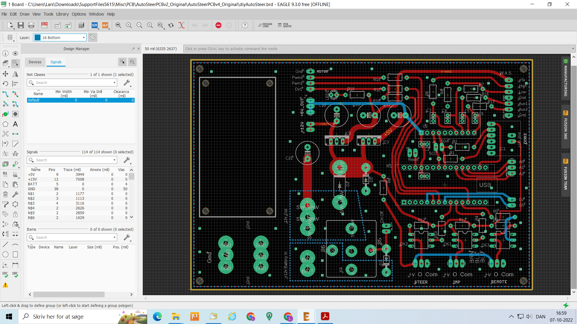
I just double checked the schematic, what i was referring to as 5v in the dog2 area is indeed 3.3v
Anyone else loving that we do not have to resize images anymore?
Hello,
How can I change the roll axis for the BNO085in version 5.2.2? Currently with the way it is mounted on my board, it is using Y axis, I want to use the X axis instead.
Thanks!
The following codes on line 155 in IMU_USB_V5_0
bno08xRoll = (bno08x.getRoll()) * CONST_180_DIVIDED_BY_PI; //Convert roll to degrees
//bno08xPitch = (bno08x.getPitch())* CONST_180_DIVIDED_BY_PI; // Convert pitch to degrees
I think it could be changed like this.
// bno08xRoll = (bno08x.getRoll()) * CONST_180_DIVIDED_BY_PI; //Convert roll to degrees
bno08xRoll = (bno08x.getPitch())* CONST_180_DIVIDED_BY_PI; // Convert pitch to degrees
Dear @CommonRail, I’m sorry I wrote before you, I’m just an amateur, not as professional as you, I hope the lines I changed are correct.
This sounds like just the thread I need - BNO085 arrived and I thought it would plug in where the MMA is, but that seems to freeze the board as it’s hanging on BNO presence check (I ripped out the CMPS check as that hung it too) when I do so. But… I can’t see any of the pictures in this thread, and the one link is now 404. Arggghhh!!!
Anyone got a working link that’ll show me what I’m doing here?
You should find wiring here if you are not going Panda or Teensy ![]()
Thanks, I’d seen those. Mostly Kaupoi mod tho, I’m PCBv2. Also, I note they’re using the side-connector, I’d fitted headers to it already as I don’t have the connector cable.
Bit of a false start with Panda today… mistakenly thought that with the Teensy/F9P/BNO mounted, that the Teensy would power the rest. Ummm… nope ![]()
So back to the drawing board on that one! There isn’t a handy build guide for Panda is there? Been looking, have got the parts list all sorted, but a kicad file or similar would be useful?
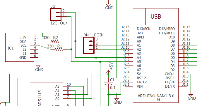
It is basically same schematics for v2 or Kaupoi v4 but board layout is different.
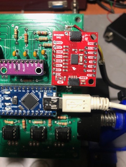
But you should just connect SDA to SDA, SCL to SCL and gnd to gnd. Arduino bno085 can take 5v but run just as well on 3.3v to v in.
EDIT: I see the old PCBv2 has been named PCBv4Original in latest support download,(and was also in support 5.45 in march) But it certainly look the same as an old file I have from november 2020.
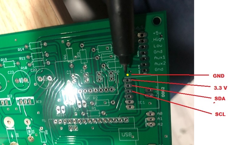
So your 3.3 Volt is the NS1 line.
And your GND for IC1 is the one closest to Nano
I can confirm that is identical to the PCBv2.
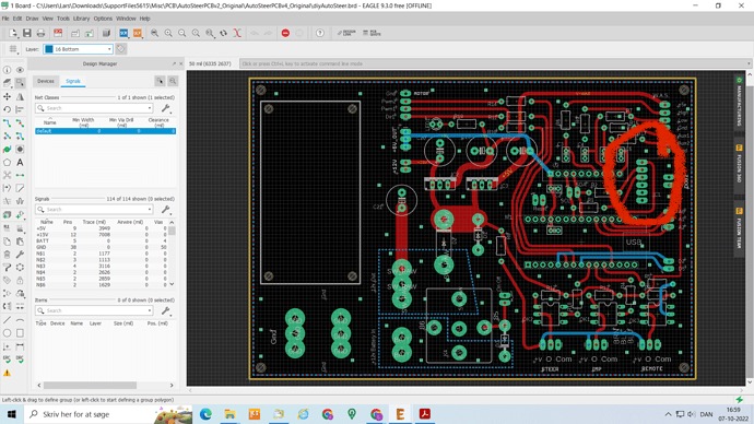
As you say, GND is Pin1 next to the nano, 5V is the
furthest pin at the opposite end with SDA next to that, then SCL.
I did this while using pcb v2, I pierced the yellow dot in the photo and used it as the GND line and connected the BNO.
Works a treat - thanks !
Thanks! My PCBs are made for BNO055 and all 085s are in the wrong position for upgrade ![]()
I had same problem with CMPS14 so mounted it separate and ran wires to the correct locations
For version 5.7 i found this line, changed in similar pattern: (bno08xRoll = bno08x.getPitch) and pitch = roll
Angle wise works like a charm. Only reverse detection very often crash the system and tractor symbol get stuck in reverse. By disabling in settings reverse detection solves the problem. Just mentioning.