Hello guys,
I finally got a system working with GPS and rtk. Now it’s about the steering: steering with motor and sensor on my one tractor works. But my new Massey 6718s I want to steer with can bus.
I got a dealership machine. They had an GPS installed, but it was to expensive and inaccurate, so it’s definitely steering ready + it got autobus.
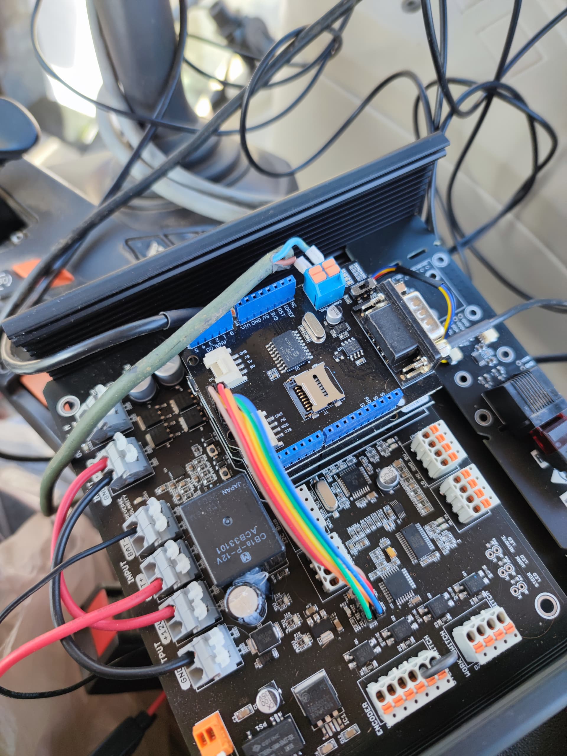
I bought a PCB from autosteer.cc it’s v 3.1
I got a seed studio can bus shield v2 ontop of my f9p mounted:
Since they have mounted a GPS system already they used the x230 connector, and hid it somewhere (because I couldn’t find it or the x184 connector besides the seat)
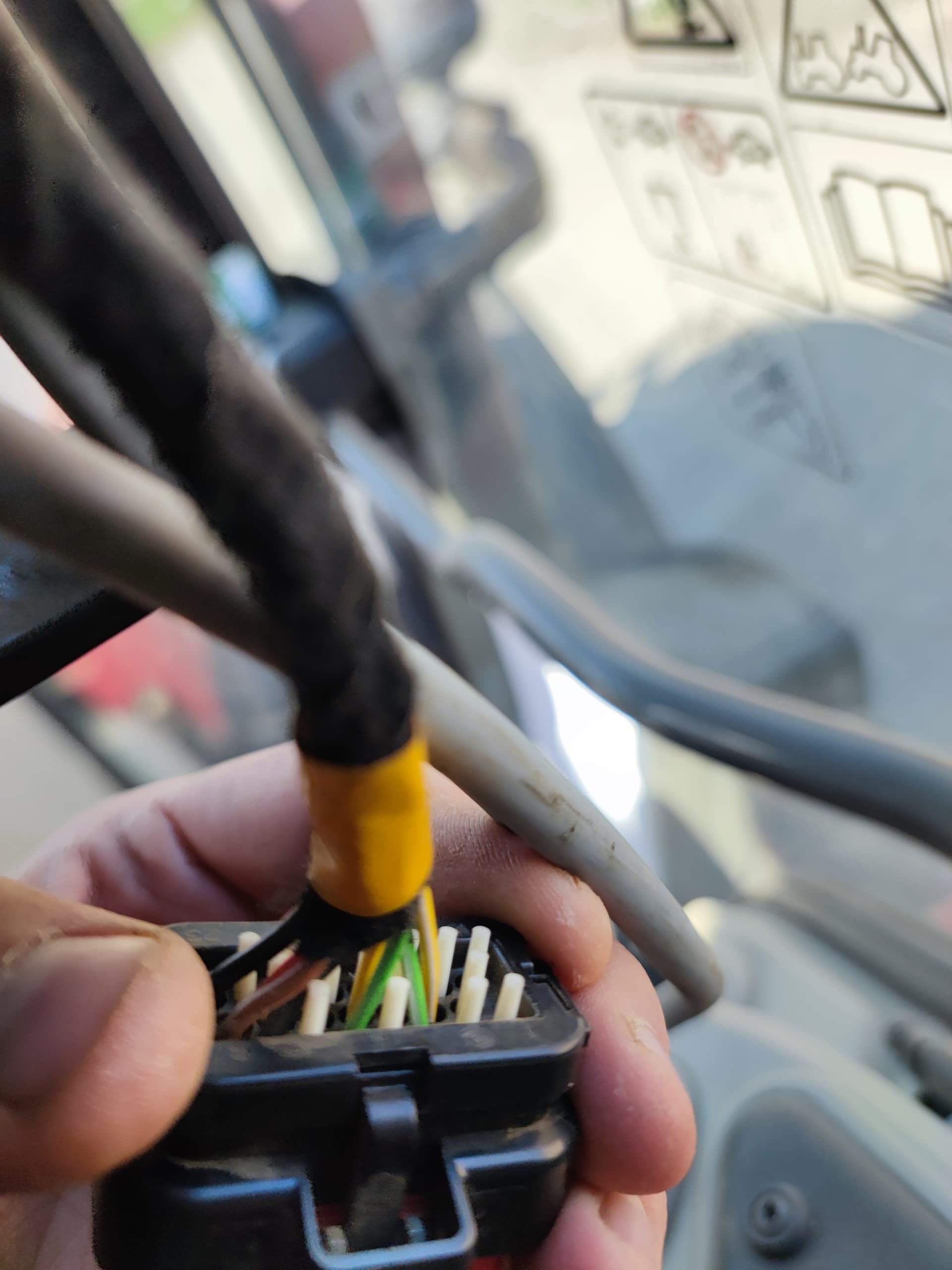
So: I connected my can h and can l to the cables which were going to the original GPS…
I found the green and yellow wire.
I get the Rx led on the can bus to flicker but the tx isn’t doing anything.
The problem is:
I uploaded tonys newest sketch with all files and the library to my adriuino board. But I always get:
Entering Configuration mode failure…
Can module failed. Freezing…
In serial monitor…
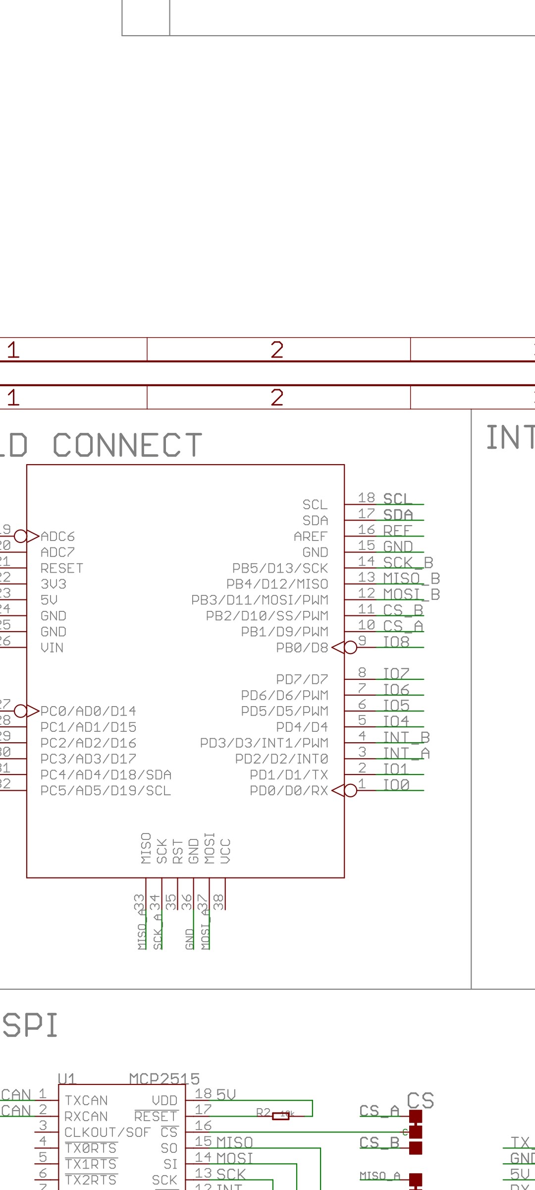
I tried switching my CS pin to 9 but ended back at 10 because that’s the correct pin for my version according to the wiki. I tried switching around the high and low cables but same result. Then I figured that the icsp connector is not connected and bridged it. But there was no success. I’m running out of Google search possibilitys, so I’m coming to you guys. Maybe one of you could help me out? 
Greetings from Germany
Ps: I also tried yellow and green striped wires next to the normal ones same result as above
I found this documentation for the v2
It says here that int should be on pin 3 and C’s on 19 but still same result.
I also tried uploading it as a adriuino uno and nano. Wasn’t sure what aortner used there.
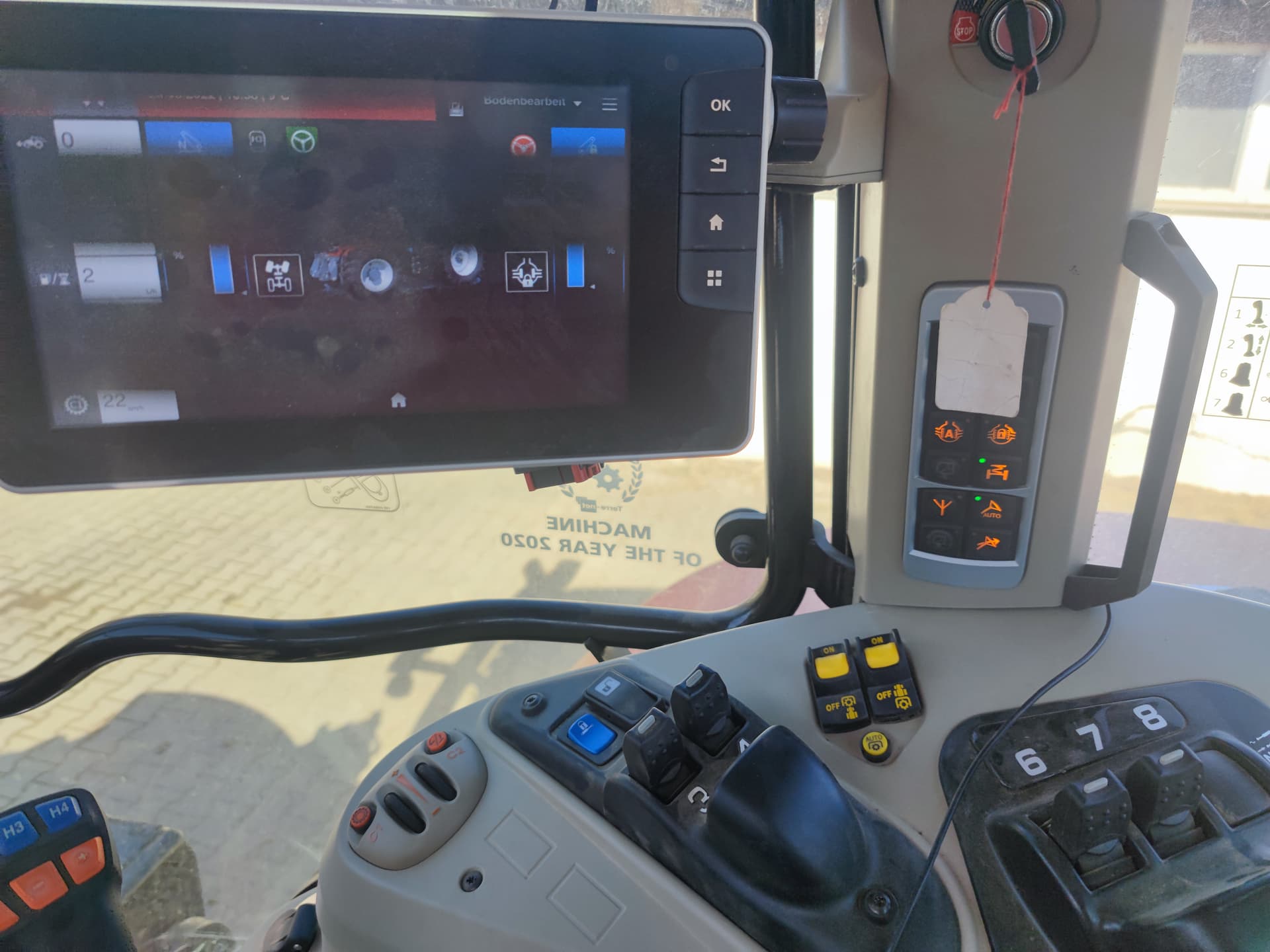
I have the auto steer button on the collum pressed and tried it with activated autobus, no difference…
Any ideas?
This will not work with the autosteer.cc PCB and is not needed. Remove the PCB and keep for another tractor that uses a steering motor.
You can use just the Arduino Uno with that CAN shield, or a better way is to use a Teensy CAN based PCB.
Thanks for the quick help.
Luckily I got 2 adriuino Uno’s laying around from other projects…
Why do you prefer the teensy over the adriuino? Because of the form factor and the fact, that you don’t need an extra can bus shield? I read a few things and that’s the only two things I can think of. Well it’s not a bad thing but I already got most of the parts I need for the adriuino build, I just got to get a second imu. Then I just have to switch the f9p shields and the monitor around instead of everything. That’s also good:)
I will try it with the adriuino uno in a few days.
Thank you a lot
Greetings
So back at it again:
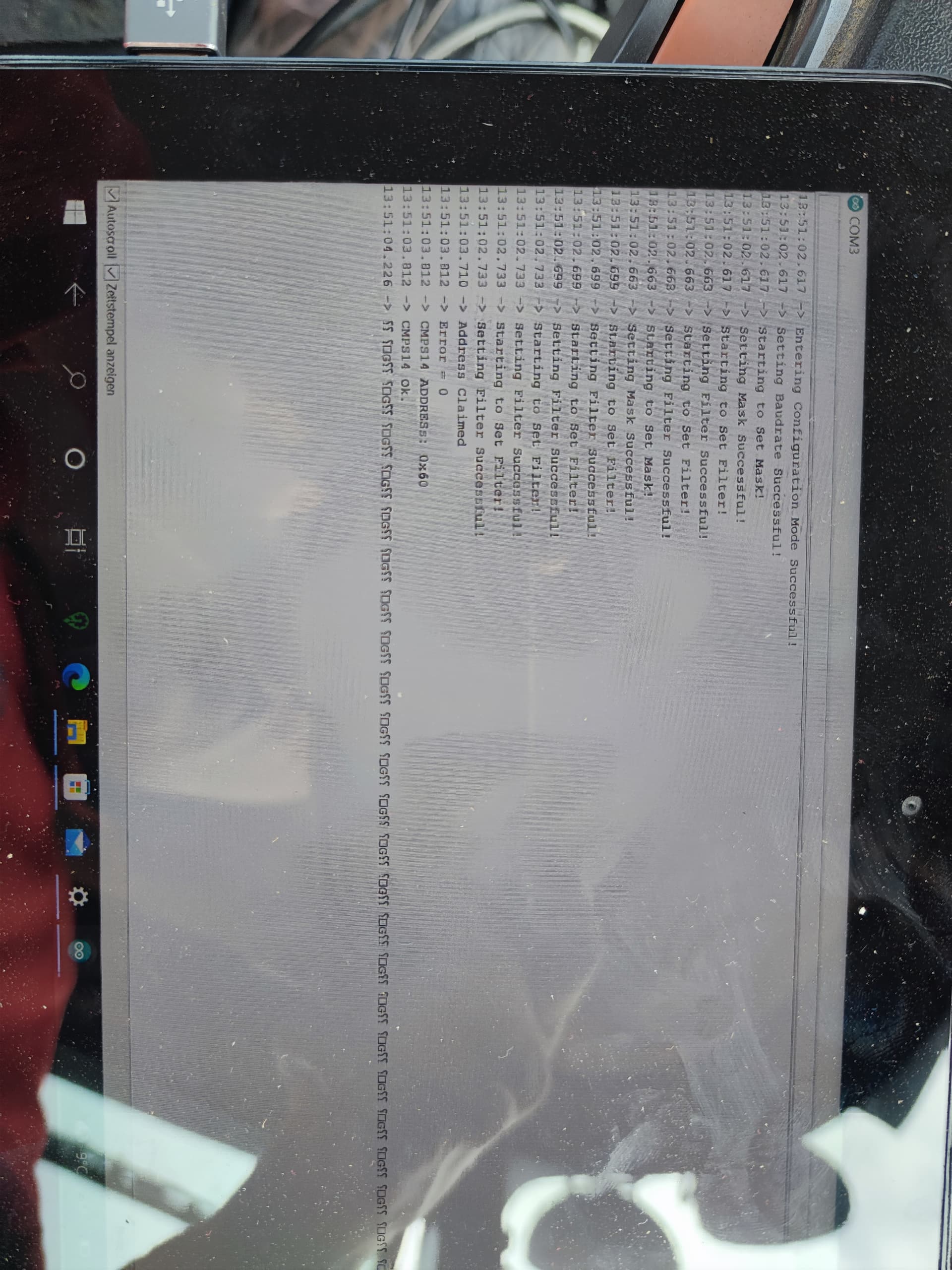
With adriuino I get the masks and filters set and it recognises the cmps14 all fine(I think)
But I get this:
It doesn’t matter where, if and if I reverse the plugs. The serial output always looks like that in the ide…
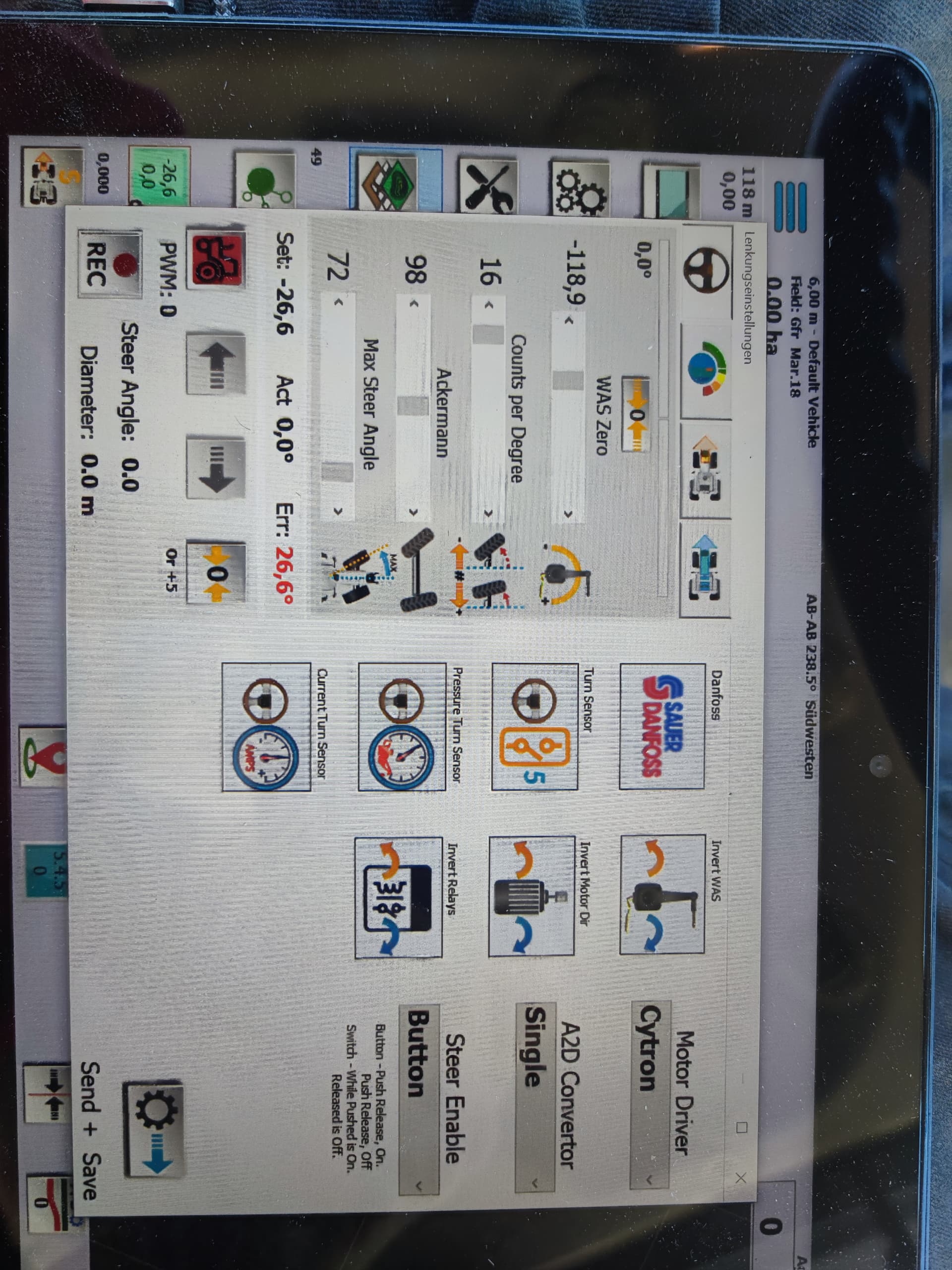
In agopengps it is neither showing the cmps 14 readings nor the was sensor readings.
BUT once I was trying and then my cmps gave readings… But only like every 5 seconds it refreshed the sensor. After some time it didn’t want to work at all anymore. Restarting everything as before led to no readings at all.
When I got the reading of the cmps I also got "something in the was section. I don’t know what it was but I got an angle and never got that before. But when I turned the weel nothing changed that current angle. The autosteer also didn’t seem to work I activated it in the Holm on the side, in the app in the bottom right corner and I tried using the software of the datatronic but nothing changed anything.
I changed nothing in Tonys code except The C’s pin to 9.
I also tried changing the clock speed of the MCP but then the tractor gave warnings from now to then that the isobus is disabled. I left the autobus button on and off but didn’t seem to have any effects…
Do you have any ideas? I would really appreciate it
Could I be in the wrong bus? But it should be the right one I think. The x230 I can’t find anywhere… Is there a way to find out?
Greetings. And thank you
Also it would be very nice to have an example how the serial monitor should look if you don’t have further ideas 
Update:
Well ok,
I ran the show all massages and AC sketch from Tony and I’m in the wrong bus, both up there were the dealer installed his terminal are not the correct busses 
I go onto a connector hunt then🔎
Update 2:
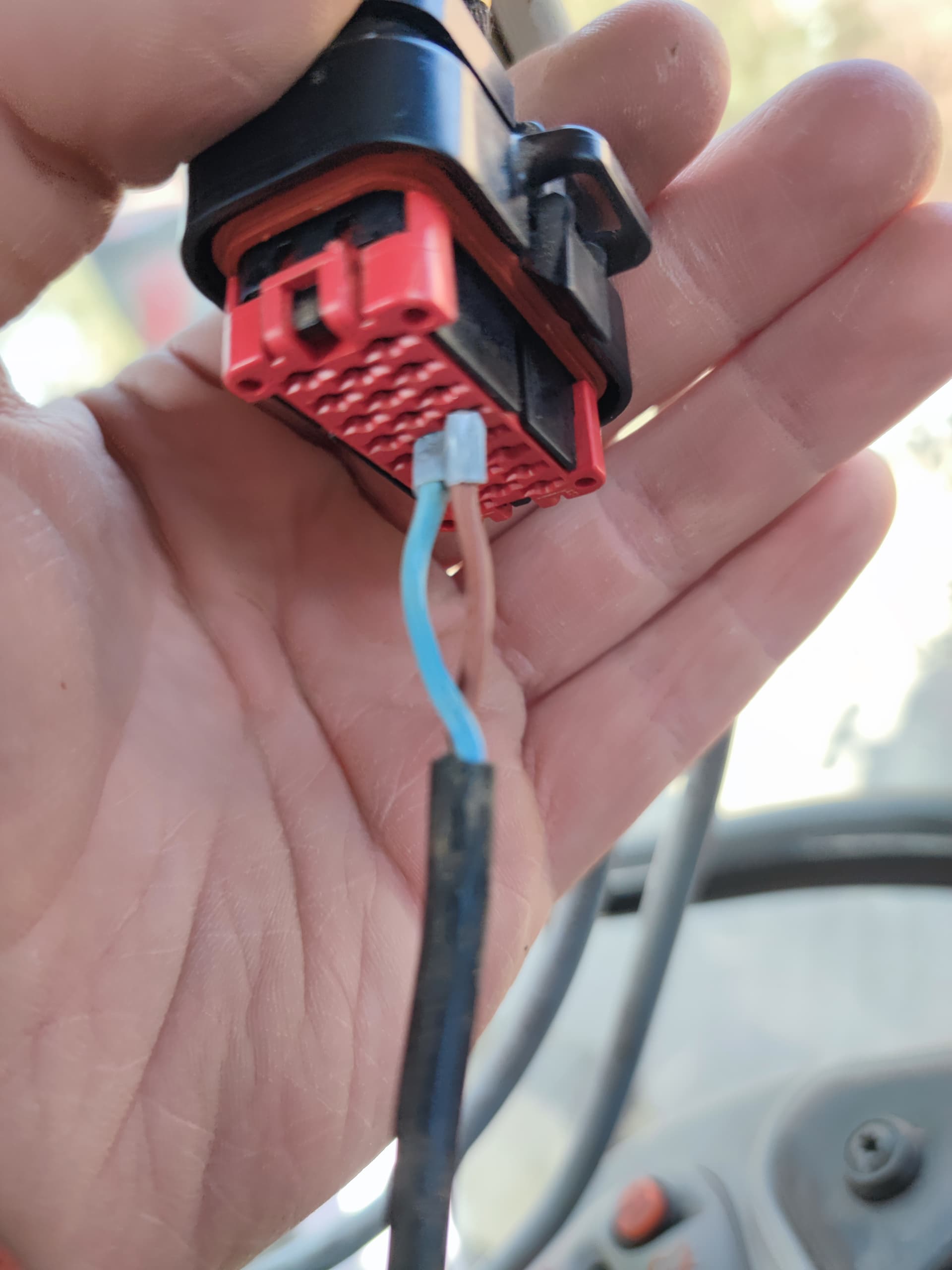
I spent about 2 hours dismantling the covers and searching for that x230 connector. I can’t find it. I had the Holmcover and the upper cover on the right side lose to look behind and the big lover cover completely removed. I tried to follow the yellow cable on the x184 but it goes into a thick cable cluster surrounded with black fibre tape. Behind that I couldn’t feel any connectors. After looking at this prise x230.pdf (472,7 KB)
I do not think that the x184cable is the same as the upper cable at the original monitor, the one on the monitor has no stripes, the one at the 184 and the document is yellow with orange. So, I will post the readings of the project 3 from the can bus for Beginners tutorial here and try the x184 if it has the same results…
Or is my tractor to new? Because its manufacturing year 09/2020…
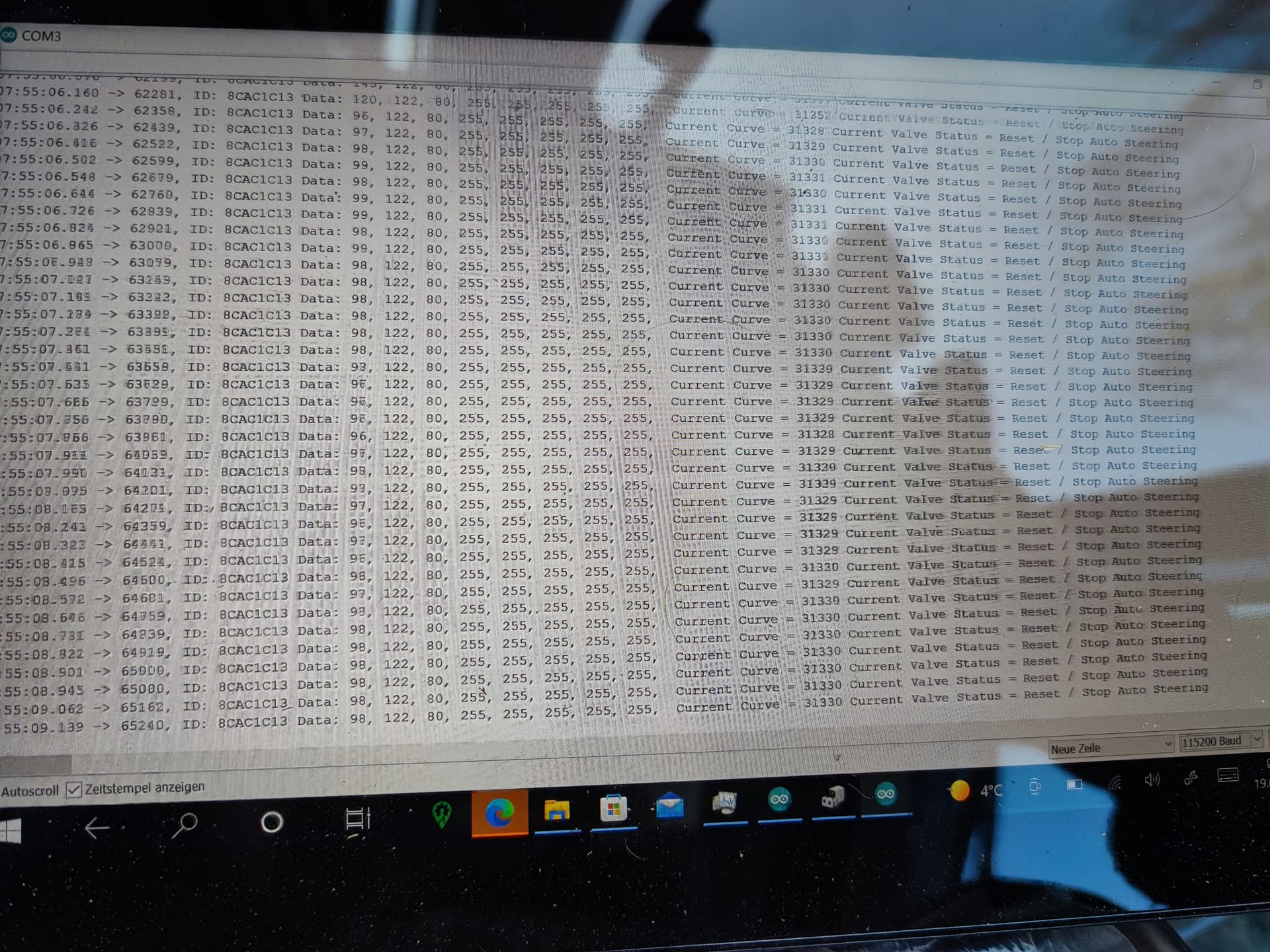
Update3: I got the AC sketch working, when I activate the button in the cabin I get readings and it says stopped/reset when I hit the auto steer button on the joystick the status disappears, the other values seem to be alright and change correctly and the read all sketch works too under the many sources are Id310 and the WAS sensor.
But when I use the valtra sketch from Tony it looks same as before in serial monitor there are the exact similar ? And box nonsense characters after initialidation.
When I go into agopen the cmps is not getting shown(I connected it via i2c to the Arduino shield(but it was working once, and I don’t know why it did that) there is no was data shown in the steering configuration window and it doesn’t steer when I press the button in the corner or on the joystick, the button in the corner only lights up when I activate it in the windows display tough. I also tried enabling and disabling isobus… Using 8mhz causes my tractor to not want to drive anymore, so I guess that’s bad
Greetings
The serial monitor looks good. Have you connected the Uno to AgIO as the steering PCB via USB?
I connected the Arduino with an short usb cable to a usb hub which is connected via an usb extension to the tablet. I got the f9p also connected to that hub.it works fine I think.
I tried connecting the Arduino to the usb directly without a hub and get no readings of the WAS or the cmps14 anyway…
In agopen I got the port which reads this set as the steering device. Tried using it as IMU but nothing changed, I got agopengps 5.5 lego
Is the serial of the agopen sketch also good? With the ? And square thingies?
I also am in contact with Val he posted the same problem on his valtra in the can bus for beginner discussion. Are maybe new valtras and Massey’s somehow different? I can send you the exact readings in a few hours if you want.
Thank you for your time guys^^
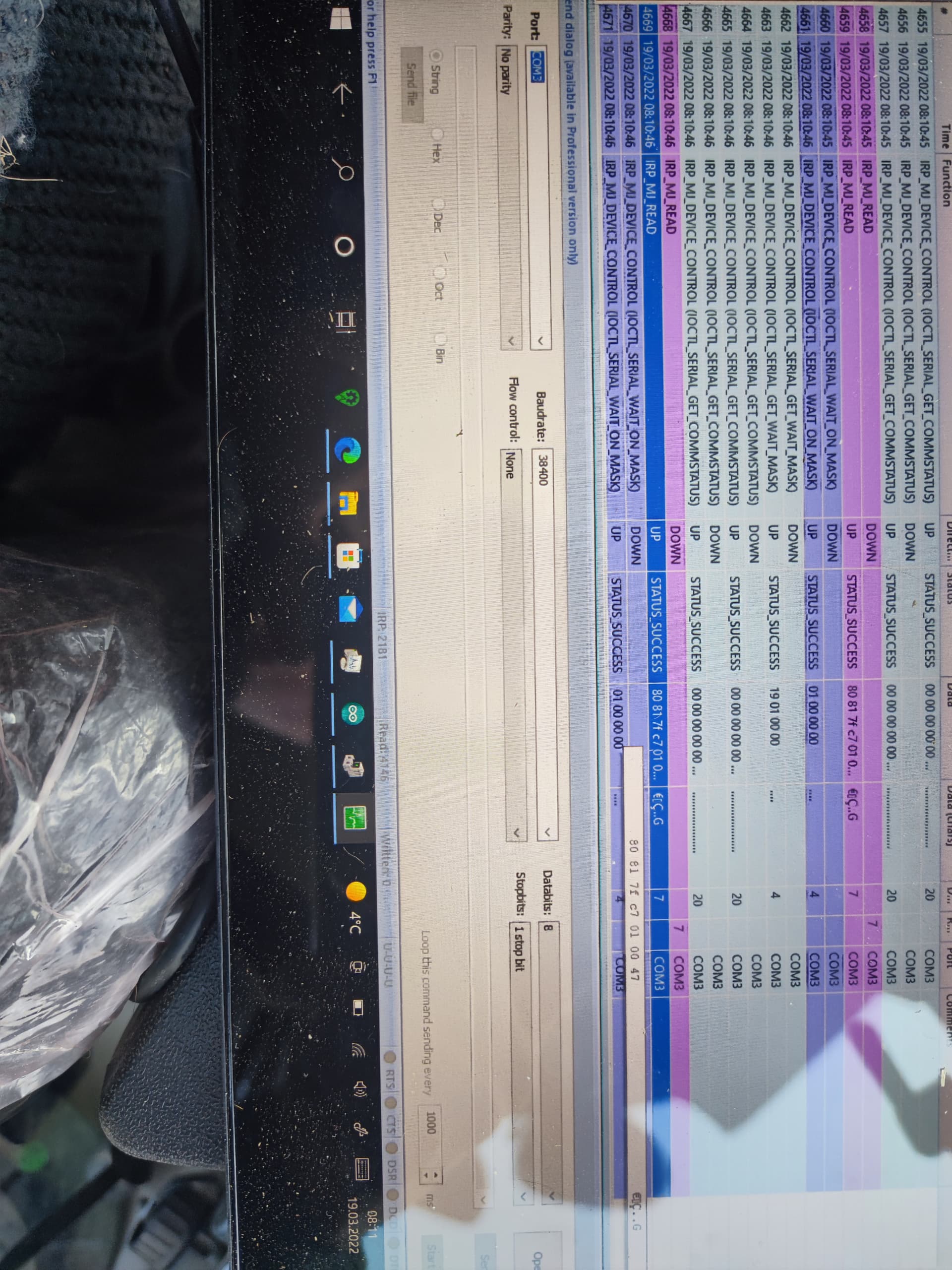
Ok: so this is what a serial monitor software reads… I don’t get smarter from it. Since agopen v5 reads the stream directly as binary I have no real way of controlling it right? Is there a possibility to clarify that stream? I think it’s a software mistake then, because I don’t even get cmps14 data but there are err=0 and cmps found message or is that normal?
The data of all the packages is the same no matter what happens: 80 81 7f c7 01 00 47
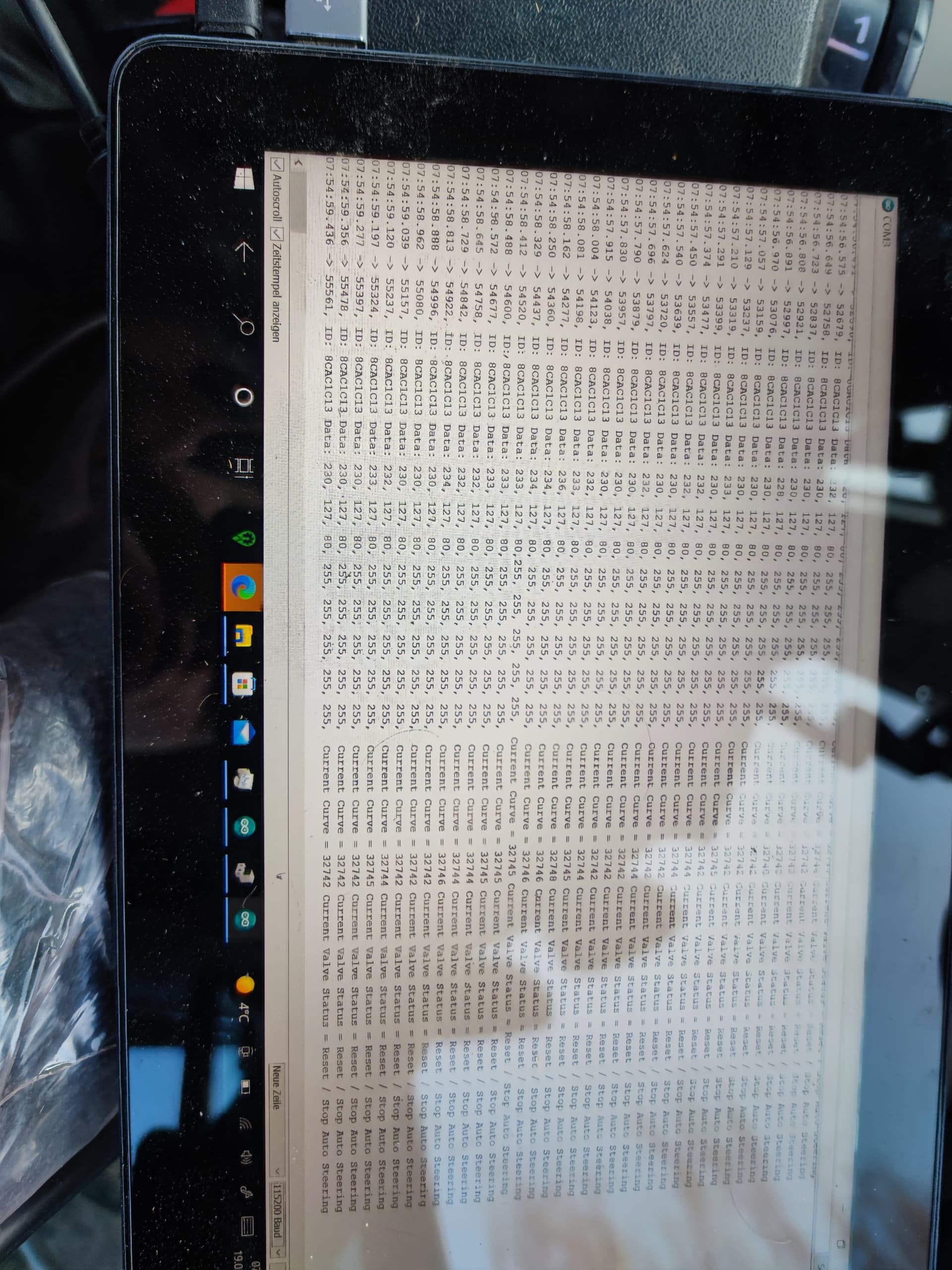
And this is curve data completely to the right and completely steered to the left
Looks good doesn’t it?
Could it be my cable it’s just normal pretty thick untwisted wire… But the data looks fine right?
Ideas?
I think it’s maybe a usb / handshake problem since I don’t even get the cmps data?
Maybe my arduino can’t handle all. The data? It’s a nano chipset on a ardiuino uno I don’t know
The serial monitor I got is also can sniff the data so I can read serial and have agio communicating with the arduino, the serial output stays the same after the cmps14 is ok phrase🤔
Just get rid of all that stuff and only connect the Arduino to AgOpen then show a picture of AgOpen & AgIO
What do you mean with all that stuff?
Should I just connect Arduino without any shields and the cmps14?
I can do that if you wish
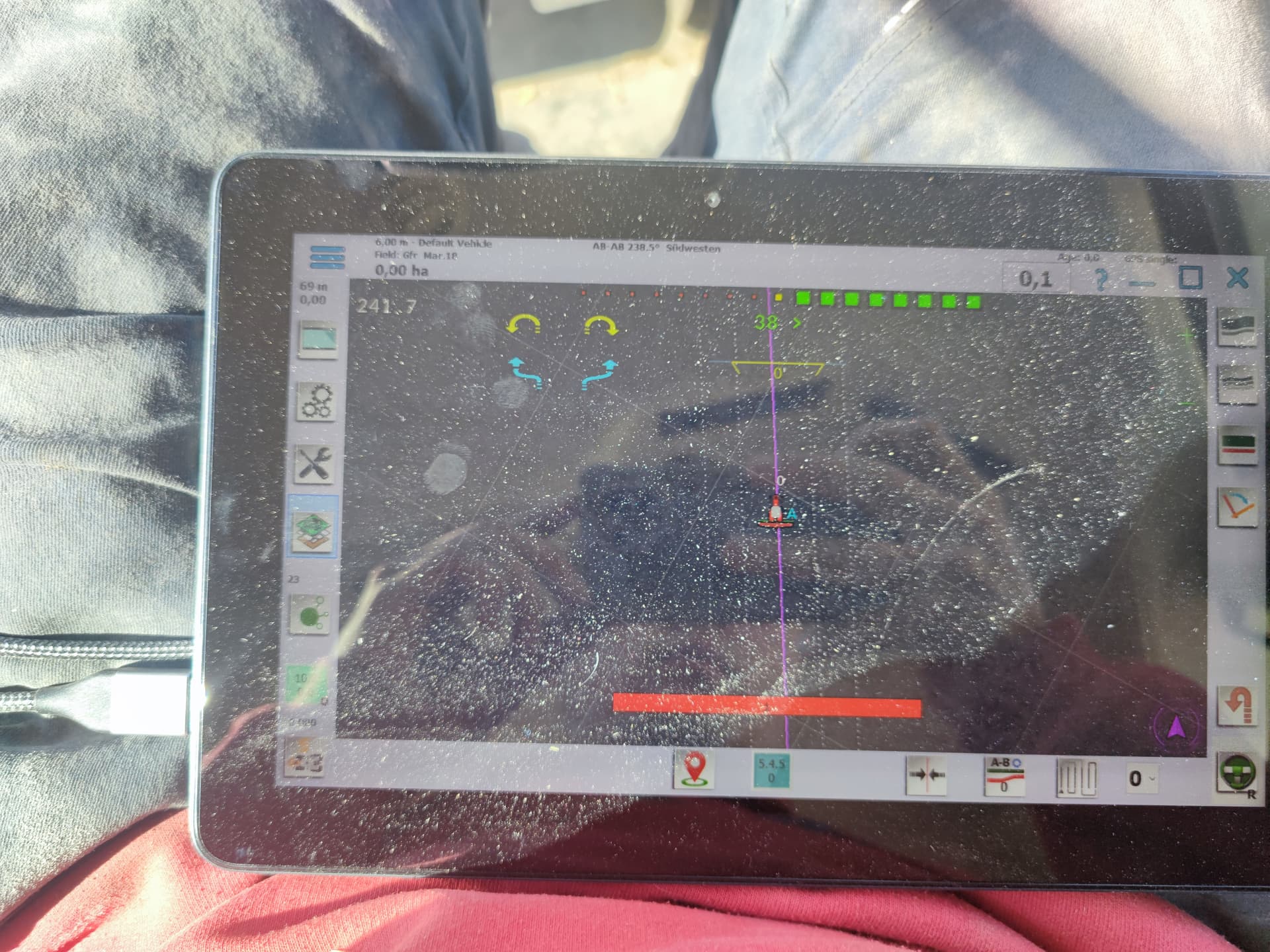
Just close all the serial monitor stuff, use AgOpen normally and show a picture of the main AgOpen page & the AgIO page
Okay dokey: finally got around to it again during the fieldwork…
Nothing changed so far
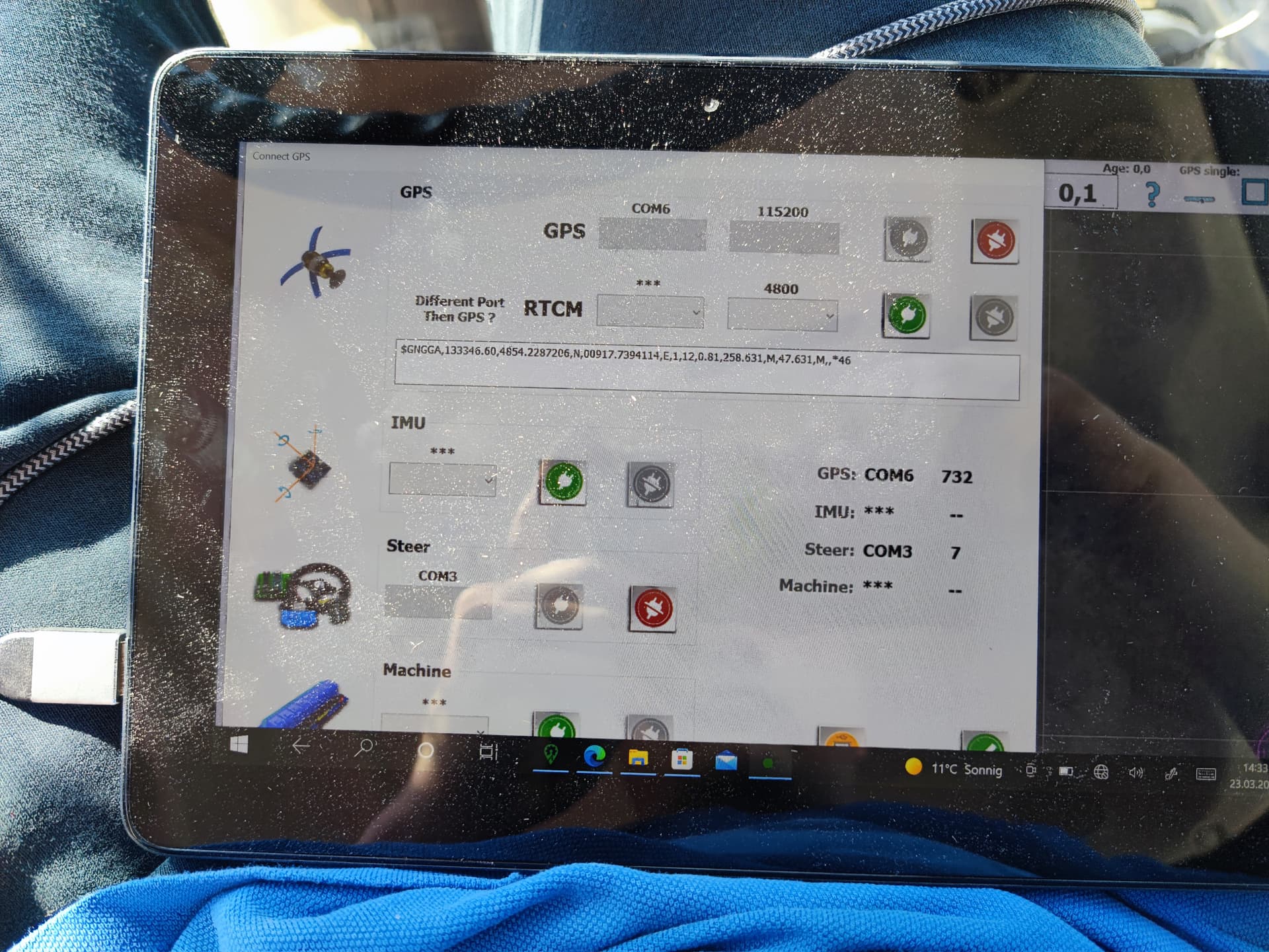
Something is wrong with the AgIO connections, is it possable you have the steering and GPS ports the wrong way around?
Hi, I can try switching them around but the GPS signal looks correct in the port connection thing.
So when I switch the ports, GPS signal gets lost and nothing works any better than before.
I try another usb b cable for Arduino maybe
Hi again,
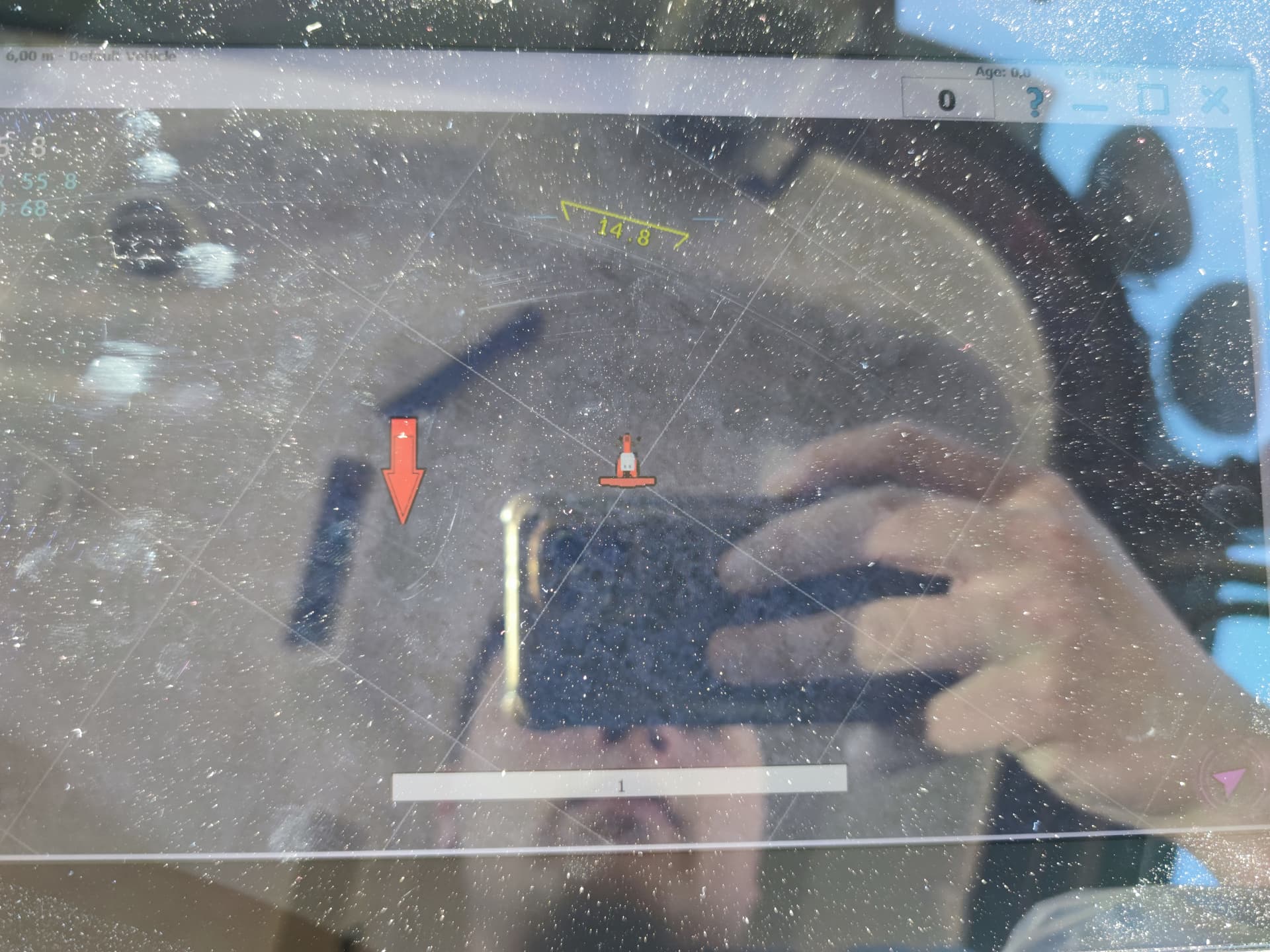
For a split second while doing nothing in the bottom right corner the arrow changed to a red one and the cmps tilt changed to 14.8.
When I tried rotating with the cmps it was frozen
I tried a new usb cable and usb hub connection.
Is maybe the usb hub overloaded with the 115200 baud from the GPS?
Haha ha!
Success!
I simply removed the ublox f9p shield from the stack of shields. Now it works!
Still needs a bit tuning and so but it steers and Shows tilt and it’s very nice.
Thanks for your input
Don’t know why since my antenna is configured like aortner uploaded here but maybe that interfiered with Chinese Arduino… Idk if anybody knows why I am keen to learn
Greetings
1 Like
You can not put the F9P on top of the Arduino, it must stay separate. Because it will interfere with Arduino/CAN shield pins and stop it from working.
Ah, hm well than that’s my bad haha, I miss read it then 
Hi There, Which connector worked for you finally and where did you find it? I have 6714s
1 Like