I know - that sucks… And the procurement of my company doesn’t expect a significant improvement this year… But JLCPCB has a components pre-order function. Didn’t test that, but nice idea.
When attempting to purchase these from JLC there are some parts that currently are on inventory shortage. These are the first 12 lines listed below. Gorm offered to help us get some alternatives to these while these shortages plague us all. In addtion you will notice some parts that the “end user” will need to provide.
I hope to order some of these PCB’s asap. If anyone wants to bulk order PCB’s with me please let me know, else you can order them directly from JLC.
Once I get them I will work with some folks from the community to see if we can get a sketch for the enclosure put toghether. More to follow but it feels like we get closer and closer to getting a hardware solution that doesnt require users to build boards and at home solder.
If you have time I would encourage everyone to “buy a coffee” on this site. This money helps fund development as a few put many hours into this project and many put in a few hours. Helping fund development is the least we all can do.
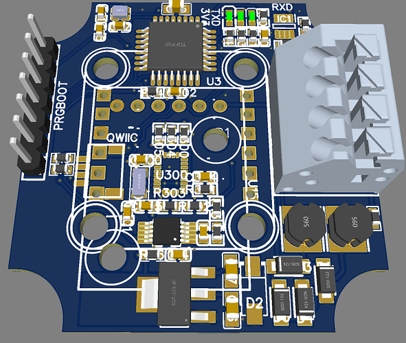
Main feature: Support of TI’s RS485-over-power-bus, so that devices like IMUs can be connected via a jerk-proof two-wire bus with power and data. The wires may even be mixed.
Watching this closely as I had built three V1.4 boards and home-soldered the tiny FE1.1s chips on and as it turns out only 1 board/USB hub is a success But as I understand none of that difficulty level in this list?
unfortunately the pinning is quite dense… you have a microscope (camera)? that helps a lot. and desoldering wire. Can tell you that is particular chip is not the problem right now, but that doesn’t help you too much. Keeping fingers crossed!
I had a final go at them and removed all previous solder work and redid them with solder paste and a hot air gun. What a relief! Half hour work for 2 chips and everything working… so it was due to messy hand-soldering although everything looked OK. Thank you for your help
I discovered that a smartphone like a Galaxy S20FE has very good optical zoom/microscope, it helped to detect/check bridges and soldering quality.
quick status update: tested ESP32 part completely now, so I can say, that the hardware is able to do dual-RTK and autosteer with just the ESP32 as a single-µC solution.
License update done to Cern-OpenHardwareLicense-S-2.0 to keep the project open for everyone in the future. Everyone is allowed to copy and produce everything of this project, but has to open her/his mods for the community.
am I missing something?
must I choose some parts and delete their alternatives?
Currently, in JLCPCB, only 1 part is out of stock. But Atmega Processor and Motor Drives are ridiculously expensive. They charge $60 for an Atmega and $30 for btN8982TA. I decided to get them elsewhere
The “error” is correct so far. You have to choose the RS485 option, so none or standard-RS485 or THV8000. Have a look at page 1 of the schematic - there is an annotation to that.
Yes, prices/availabilty is a nightmare these days. Personally I would leave these parts unmounted, source from somewhere else and solder yourself. But that is not easy in some cases.
@GoRoNb , Thanks for the all input & work you have put into this,
I am a farmer that has no real experience in Electronics, what I look for is autosteering not section control for now.
For the beginning, I planned to go with 1 ardusimple, then IMU. Maybe later on when things start to become more clear for me I can switch to 2 ardusimple setup.
For this reason and the beauty of your board, I planned to order the PCB. Watched your video here:
and when JLCPCB gave the placement error I mentioned in the previous message, I read the documentation over and over again until I feel confident.
So after feeling somehow confident I have chosen not to include RS485 and go for Power Line Communication, I also excluded items for Danfoss since I think I don’t need it.
is this the correct approach? In github you mentioned that:
Only mount R31, R32, if ESP shall forward serial data to the (piggyback) section control unit.
Only mount R49, R50, if ESP shall forward serial data to the steer unit (Atmel).
For 1 ardusimple assembling R31,R32,R49,R50 a problem?
After all, as a beginner would you recommend this board or PCB v2 . PCB v2 seems much simpler to me but requires soldering work.
if you plan to upgrade to dual, you should go for the V2. If you want to run Brian’s original code, you only need the Atmel µC and no ESP32. Even for dual, I wouldn’t use an ESP today as you can connect both Ardusimples via USB.
I know, I should publish different Bills Of Material (BOM) for different use cases… Work for the next time…
USB hub to connect to one or two Ardusimple + one external device (e. g. IMU or GSM stick)
internal or external IMU option (BNO085 / CMPS14)
Unfortunately JLC is charging extreme unacceptable costs for some components , so the only chance these days is leaving those parts unmounted, source from somewhere else and mount yourself.
Thank you, that will help most people like me. Just a question before placing the order,
If I am gonna use electric steering not hydraulic do I need this “BTS50301EJAXUMA1”? Cant find a single stock on this component.
I am getting repeated coordinate errors on the following parts. I uploaded both the screenshot I got from JLCPCB and xlsx file they provide. Although I am getting these errors, I can proceed to checkout and complete the order. Should I proceed and ignore those errors? I just downloaded the production data from the Github page.