One of the endless frustrations for single antenna is that the imu is never coordinated with the gps position since they come from 2 different sources. I’ve been thinking about the idea of instead of just an imu module, read the gps as it is being sent, take a reading from the imu at the right time, combine all the required data into a sentence. Much like PAOGI does with dual.
I hope to be able to set up a test rig to roll the antenna on a pole and determine imu timing etc to be able to match the reading of the imu with the time the fix was taken. It is easy to just delay from the last reading and then read the imu at the right time. This value could also be adjustable to “tune” the 2 until the best results are achieved. Take all those individual values, put them together into a $PANDA nmea sentence that AgIO can parse. Again, just like the PAOGI sentence.
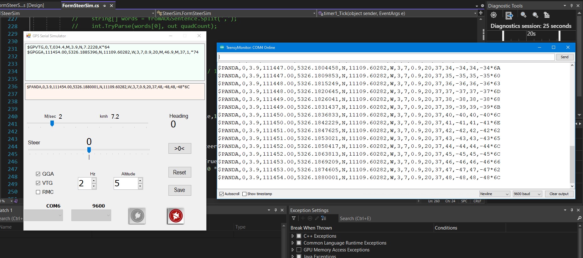
So i’ve written a small simulator that puts out GGA and VTG which gets sent to a teensy 4.1 Serial7 hardware uart. The IMU is also wired into the I2C of the teensy. The “normal” usb port can then be connected to the gps serial of AgIO, and all the readings sent off to AOG to do correction with the data coming all from the exact same time. Finally.
I will keep updating here, sharing the joys and frustrations…
The sim on the left and the arduino serial monitor showing what would go to AgIO. Since it is the Teensy 4.1, it also has udp.
So would be possible to combine it into one teensy autosteer unit passing GPS and steer via udp. Something I’m looking at for my teensy CAN steer system.
@nut has NMEA coming into his WASless teensy code so should be possible?
As long as the code isn’t blocking, the Teensy obviously has plenty of processing overhead.
Ya there are a lot of possibilities of combinations. Teensy has ethernet so anything can be in serial or udp. Also have yaw-rate along with pitch roll and heading in PANDA
I have the Ethernet connector on mine. As it’s cold outside now (not Canada cold but nesh Brit cold! ) I’m going to annoy the wife and kids with my GPS roof panel in the house tonight and play with Ethernet and also a remote CAN IMU idea to put the BNO085 in a more suitable low down location.
This is exactly the setup I have for the WASless testing. The Kalman filter fusion code calculates the fused heading, yaw rate and speed, you could just dump those into an NMEA sentence. It’s actually using the fix2fix heading to update the IMU integration, and reverts to IMU only for speed under the threshold. If GPS goes bad, it trusts the IMU more. You can tune it with the covariances, trying to update it to use the GPS position accuracy estimate for those. Check it out from here:
Might have, might not. Just gets really tedious trying to worry about the resources and try to optimize the code for that. ATMega328 8-bit vs. 32-bit Teensy with a floating point unit is around 300x more powerful. Plus you got native ethernet, 3xCAN, hardware serial etc. in a board that costs around 30-35 eur. The only “problem” with Teensy is that it’s hobby hardware, i.e. not really rated for industrial environment, but so is Arduino and those seems to be running with no issues as well…
@BrianTee_Admin while we’re at it, it would make sense to add dead reckoning to the GPS as well, I have some alpha code on that in python, need to start porting to C++ at some point, would get rid of jumps in case RTK drops for a second or two…
Not really, and not related to heading at all. I mean if you lose RTK fix, you can use the IMU accelerations to calculate the GPS position while waiting for the RTK fix to return.
The only problem with the nano is the uart (serial input output capability) as the software serial can in no way run at 115200 baud. Any other processor that has at least 2 hardware serial ports would work - the bonus of the teensy 4.1 is the ethernet already on board.
The nano can easily do the processing - not a problem at all.
One of the biggest challenges is antenna offset and moving the fix to the correct position - but before you do you need a heading - but before you can do heading - you need 2 fixes - but before you can 2 fixes you need to fix the offset - but before you can fix the offset you need a heading - but…
I’m curious to see how your code will work in the field. That is always the acid test. But absolutely, a full dead reckoning system would be super cool. Thought I would start on the platform and get the basics of antenna correction hopefully kind of working. Something commercial units do with ease as they have all the data in one spot, not bouncing around serial ports for a while then fusion occurs.
Do you mean the physical offset between the antenna and the IMU? I’ve been lazy so far and just stacked them on top of one another for testing. To be done is to implement the lever arm calculation to move the GPS data to the IMU coordinate frame.
As it’s integrating based on the rate gyro, the only absolute heading reference used is the rtk fix2fix heading, as soon as that’s available for the first time. Then it just keeps integrating and correcting the yaw rate (taking into account the pitch/roll corrections as well) and calculating the bias. If speed drops below threshold it reverts to IMU heading which is fired to the last RTK heading. That’s still missing from the ino but is tested in the python code with real driving data. So the algorithm is more or less giving the course of the vehicle, not the heading (i.e. where the nose is pointing). If you want that, then the filter needs to be done in a different way, i.e. go to direct IMU integration when ever there’s heavy enough turning present.
So far I’ve only tested it on a passenger car driving around, to be tested on the tractor in a few weeks time.
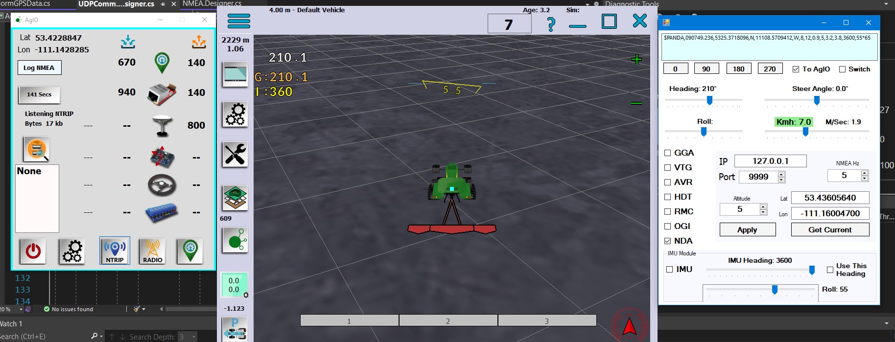
Modified the PGN that takes data from AgIO to AOG so now $PANDA can work. Added IMU heading and roll, but still need to add pitch and YawRate. Then i think everything is in AOG needed - whether needed or done externally.
Why does that matter in rigid body motion? The angular velocity and acceleration are the same where ever you measure, the linear accelerations are not. Same with the fix2fix, it gives the same course regardless of the antenna location. If using the gyro rates directly in the filter it shouldn’t matter where you place the antenna and IMU? Might be that I’m missing something as well?