Configurable Section/Hydraulic/Tram in AOG

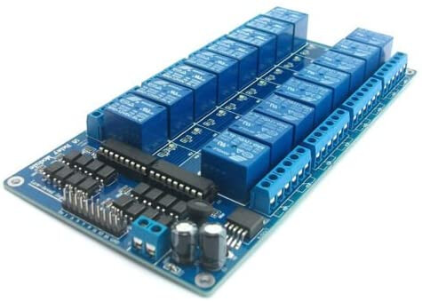
One of the biggest challenges i think is the machine section control. It should be really easy - but no one sets it up the same. How do you make a diagram for connections that are all different for everyone.

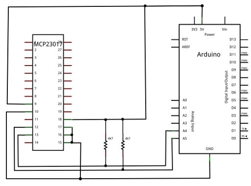
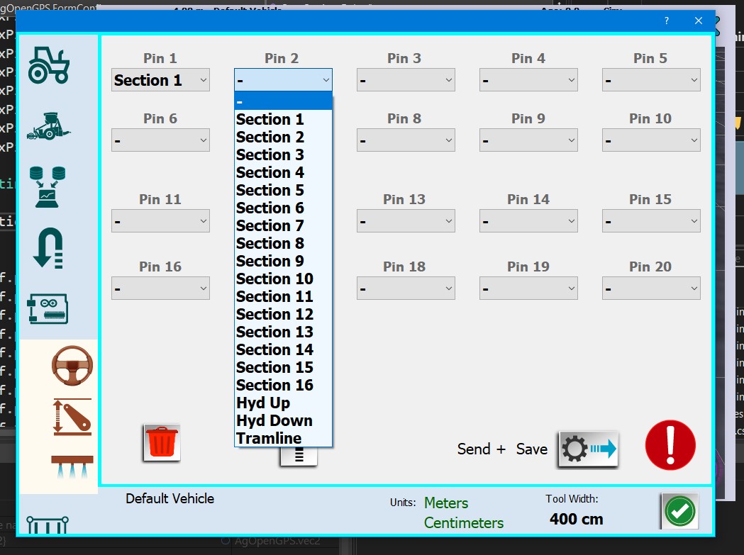
Solution: Let the computer do the work. Set the pin for the machine board for the function you want to do, let the firmware direct the right control to the right relay (pin). Hopefully now we can build a single board with 20 some pins for connection, and you can just set in AOG what you want to have on those pins. Hook up and go.

I’m hoping this will go a long way to making it easier. This way you can just save the config for each vehicle, rather then needing to program an ino to make any changes.

Happy New Year to all and have a joyous holiday if this is the time you celebrate.

12 Likes

Thanks Brian so good idea and easy to use

Assign pin on this dedicated board like our machine board today is good

but also few dedicated pin to the autosteer board for D2, D5, A1, A2 for small project like Hydraulic or Tramline or just 1-2 Section


Other question on the past you discuss about MCP23017 is it forget it ?


Happy Christmas

I think that is still the best way to make a board using the MCP - but if only a few pins are needed, a simple nano and a few relays is very simple to make. And now can be set to to what you want to do.

The same type of programming could be applied to autosteer board as well, defining which pins did which function.

Andreas’s autosteer board design uses the section control board via I2C

1 Like

Thanks for the answer and sharing this feature

After Christmas we will have to nail down this all a lot more to be standard. Relay data gets sent to both the autosteer port and the machine port so everything can pretty much happen anywhere.

The whole technique should work with any existing designs of machine module already made - except now with easy config of which output does what without changing ino once updated

This is a very good solution, one relay box with a multi-pin connector can be easily adapted to different machines, e.g. sprayer and seeder. Maybe in the future it will be possible to extend it with configurable PWM outputs for dose or equator control? Can the standard be based on a controller with more inputs, e.g. Atmega 2560?
Happy Christmas

Good developments again Brian!

Would it be worth programming this to be used with a 16 relay board already to start with? Of course CAN boards and I2C would extend the numbers even further, but 8 is very little outputs e.g. for a sprayer. Arduino Mega machine board could handle multiple 16 relay boards, which would already make it possible to control individual sprayer nozzles (or row actuators for seeding) on most machines.

Some time ago I modified some ino to use a 16 relay board with Arduino Mega to connect in parallell with Amazone Amaclick, which has 13 manual section switches. Never had the time to take it forward from a desk test, but seemed a feasible retrofit.

Individual nozzle control is where the industry is going, coupled with multiple spray solution booms and real time weed/disease/pest identification and immediate action. That requires plenty of outputs and at least Arduino Mega has all that available with less than~10 USD price difference compared to a Nano. I see very little reasons to try to squeeze module size at the cost of functionality.

2 Likes

Well i think the best way is using the MCP23017, 2 of them and using 24 outputs and 8 inputs. Each chip has 16 bidirectional ports. You can use 7 chips on a single nano providing 112 individual outputs controlled by a single nano!!

The only question maybe is it better to build a board with all the relays on it, or have a board that has the relay line level outputs and then the user can choose how many relays and or what kind of relay they want to use. The chips use the I2C lines only and free up all the other pins for whatever - like pulse output.

Easy to use an 8 ch and 16 ch relay board like these.

Thoughts?

image

image

Most often we need dpdt relays.
Another problem and a serious drawback is the poor quality of most Chinese relay boards, relays often stop working.
I think the most sensible thing is to build your own boards based on good quality components with the type and number of relays / mosfets we need.

1 Like

You are right that the Chinese relays are of poor quality, another alternative is to replace the relays on the existing relay board with quality ones without dealing with a new pcb. (panasonic-finder-omron etc.)

Not everyone wants to build their own board though. I agree, a 16 relay board with drivers and power supply for 16$ (about the cost of a good relay) is not the best reliable solution either

I’ve also had some relays not working on these Chinese boards and would consider Solid State Relay board for some purposes better (at least no loud clicking all the time).

If using I2C as the protocol, would it be simple to bypass/leave out Arduino alltogether from such machine control relay module, since the commands could come directly from AOG to the relay board via USB to I2C converter.

There seems to be also possibility to have a board with direct USB command that appears as a serial port itself:

Note that the SSR board you linked to only works with AC 100V. Will not work with 12 VDC.

Hi Brain,
We have been using section + hitch control for headland managment and work switch options in the “Most brands” Teensy CAN code.

When its time update all this machine stuff the following would be really helpful for both CAN and normal Arduino Nano users.

From what I see the current machine config PGN is:
5 = Rasie time
6 = Lower time
7 = Spare
8 = Set0 (bit0 - Invert Relay, bit1 - Enable, bit2-7 - Spare)
9,10,11,12 = Spare

General Fix 1
ConfigTool.Designer.cs - Remove line 1306 (so text always = switch controls manual)

General Fix 2
ConfigModule.Designer.cs - Uncomment line 341 (so the warning pops up when enable is selected)

Hitch Module Page & PGN Mods
5 = Rasie time
6 = Lower time
7 = Workswitch Trigger Height 0-100%
8 = Set0 (bit0 - Invert Relay, bit1 - Enable, bit2 - Use Hitch % Trigger, bit3 - Use Section1, bit4-7 - Spare)
9,10,11,12 = Spare

Next to the “Invert Relay” button we can have another two buttons.

First one “Use Hitch % Trigger” (byte[8], bit,2) and then have a box under to enter number 0 - 100% (byte[7]). Then we can use this to trigger the workswitch at a set hitch height.

Second one “Section1 Controls Hitch” ((byte[8], bit,3). Sometimes you want to use section control and not the headland to control hitch.

Could be used by both the CANBUS or Arduino Nano systems.

2 Likes

Perhaps version 6 for changing the form in config? All the manuals are done, pictures made etc.

Can’t remove line 1306 as that is used by others. Why do you want it removed?

Line 341, ya that was just a decision, you need to make one of the other settings rather then just being able to send and save default.

Just ideas to make it even better when your in there adding all this other machine stuff I’m sure that’s v6 too?

Line 1306 is misleading. Because the text is on the button so like everything else if it’s green it dose what button says, if not green it won’t.

Now you open page, text says “controls manual” so you click goes green and it operates manual as expected.

But now if you want to control auto, you open the page, text says “controls auto” and its green :thinking: so the poor operator is confused. All because that text is now wrong, it should always say “controls manual” then the operator would deselect the button.

The enable warning line catches you out if everything is where you want it and you just enable or disable and forget to send.

1 Like

Added to the click function of checkbox to update the text. Should work as expected now. Thanks for explaining it.

The joy of 5 million different settings…

1 Like

Hi everyone I’m having a slight problem with section control. I have it working perfectly in simulator mode but as soon as the GPS is connected all four relays just pulse on off continuously when they should be off. When they are switched on with ag open they will stay on just won’t stay off.

But when you use the sim, it all works?

Connected to the machine module, not the steer port, yes? Using Serial or udp?

Thanks for your reply I have got it all sorted now. It was all down to not having the f9p set correctly.