I have this pressure sensor, link is above, and I would like to know how to set it up. Until now I have been using a different sensor with voltage output and I purchased this sensor and planned to use it that way as well, but I noticed that it also has the 4-20 ma option. So if I wanted to us it that way, am I understanding correctly that I would power the sensor with five volts, make sure the jumper on the AIO is in the correct position and then it should work? Is there any reason why this doesn’t work?
The specs say 8-32 V supply voltage for 4-20 mA output, seems five volts is not enough but this should not be an issue as you can also use 12 V.
I’m not familiar with the AIO board but the current signal should be terminated with a proper resistor to ground to obtain a suitable voltage range for the AD converter (or what ever is reading the signal).
Which AIO?
I’ve been using one of your micro boards that I got when they first came out a year or two ago
Like @NorthernFarmer said, your sensor’s spec shows power supply of 8-32V for the 4-20ma output sensor, connect it to 12V. The v2.4 Micro AIO should be ready for a mA sensor on the pressure input unless you’ve modified it for your previously installed voltage output sensor. So originally it had a load resistor that converts the mA signal to a voltage signal but if you’ve modified it to work with a voltage signal then you’d have to revert that modification.
Ahh yes I forgot, I did modify it to use voltage signal
I also have a couple of 4.2? boards that I’ve never used yet. What I’m gathering is that for them I should be able to simply connect the sensor with 12v supply and should be good to go.
V4.x boards were changed to primarily support voltage sensors but with an easy way to support mA sensors. I think you only need to add a load/burden resistor to convert the 20mA to 5v (or 3.3v, can’t look at schematic right now). V=I*R
Silly me, I just looked again and I actually have the voltage output model of the sensor. So am I correct that with the 4.2 standard boards I should be able to use it without modifying the board?
The board is setup for 0-5v input, with an extra resistor you can use 0-12v too.
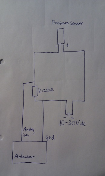
Not quite. + & - goes to the sensor but a 3rd connection (it’s signal output) should go to Arduino analog input with the burden resistor to - (gnd).
@whiterose is right with his drawing for a 4-20 ma sensor.
On V4 AiO boards the external 250 ohm resistor is not needed, you can instead use the 4-20 ma jumper, it connect an onboard 250 ohm resistor.
I always use it this way, my sensor has 2 wires, it outputs 4-20 mA > 1-5 volts.
And I fix it with the map command. My sensor is 60 Bar.
val = mapfloat(val1, 11.75, 60, 0, 60);
float mapfloat(float x, float in_min, float in_max, float out_min, float out_max)
{
return (x - in_min) * (out_max - out_min) / (in_max - in_min) + out_min;
}
I stand corrected. I expected the sensor to use a common ground.
Quite a clever device this current output sensor. Sort of floating ground that it creates itself and then only needs two wires. Since it is current output, the accuracy is not affected by wiring resistance.