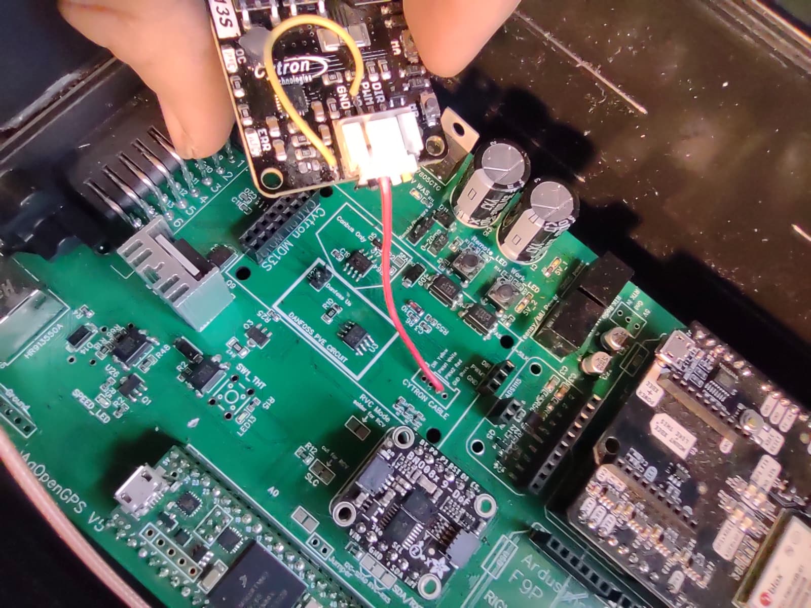
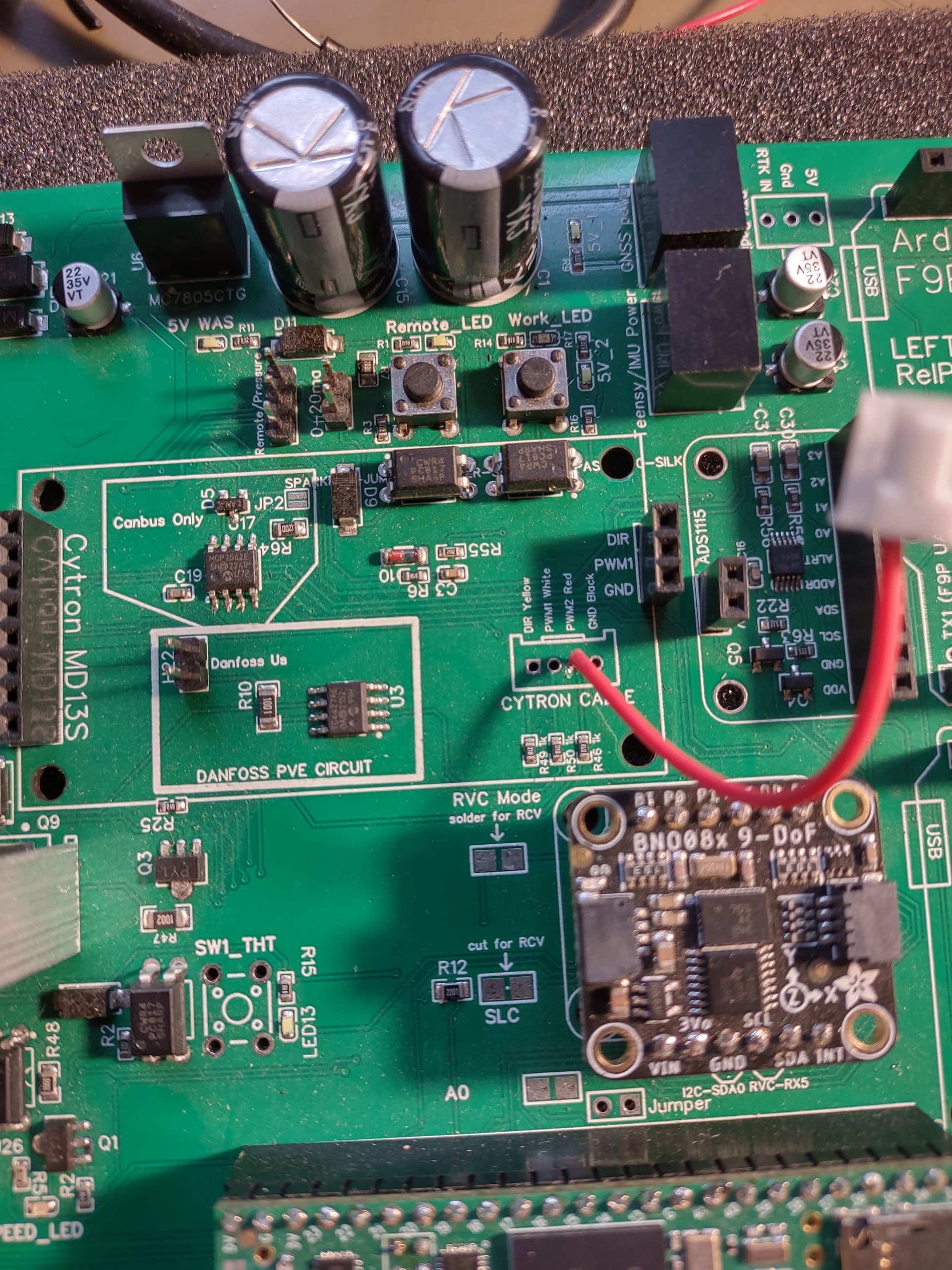
Hi! Could someone help me understand how the Cytron has to be connected to the v4.5 Micro PCB? I saw a post of someone’s connection on the Standard board, but I just want to make sure I’ve understood it right before I solder it.
These are the photos somebody posted. What is the yellow wire doing? The red wire makes sense, but the yellow wire looks like it’s soldered to the tiny metallic piece on the Cytron labeled 1002. Thank you!
Both the yellow wire and the red wire are for the Cytron Modification. It’s for if you are using a motor, it helps reduce the drag from the motor when steering manually. Searching “Cytron Modification” should show some threads on how to do it.
Honestly, I wouldn’t do the cytron mod at all. Some think it’s andawesome idea, but in my opinion, you can add a relay and reduce the drag even more, and you don’t risk ruining the cytron.
Note that if you aren’t using a motor, you don’t need to do the cytron mod at all. Just solder the 3 pins facing down on the cytron.
4 Likes
This clears things up, thanks David. My only other question is around how to solder the 2 by 8 and 3 by 1 headers on the Cytron.
Compared to the other parts it seems a little different.
- The outer header pins run along the outside edge of the board (as opposed to through holes in the board)
- People seem to ‘bridge’ the connections on the 2 by 8 header section to create just 4 combined blobs of solder at that end
Am I understanding this correctly?
Yes. That is correct. The input side itakes a little care when soldering but can be easily done. There are only 4 connections on the output side, each one using two pins.
1 Like
Solder them in place on the main PCB
1 Like