3 month update:
The system with the DS18B20 is much easier to deploy than the DHT22 system. However, I am running into system reliability issues using this setup. I am only getting about 2-3 days of readings using this system, whereas the DHT22 was reliably reading the sensors for several months (the ones that survived the grain bin). The DS18B20 is WAY more robust and WAY easier to deploy, but I need to figure out the signal loss issue.
I run the sensors on a 3 wire setup (power/ground/data) .And m_elias was right, the DHT22 would need some kind of hardening to be useful and the DEFINITELY scale better:
Does anyone have code that has been stable using these sensors?
Does anyone have a waterproof DS18B20 sensor that has been working?
I bought the cheapest bulk amazon sensors. I am trying to figure out if my system is unstable due to code or hardware.
Ds18b20 multiple sensors.
Hopefully link works. I was watching this today. May or May not help you. I was thinking about using them for anhydrous knife monitoring.
Thank you for the help. So far I have been focused on the software side of things. I dont know why, but I am hoping to avoid moving to C++. Its irrational, but I am trying to get the micropython to work despite it not being a machine language.
Quick couple of updates from my end:
I think I have a working theory on the programs failing 2-4 weeks into deployment. I think that the failure is occurring due to a memory leak. I have 2 non-exclusive candidates. First, I believe that the over-the-air update from the WebREPL combined with a print functions stores in memory creating a memory leak. As the program continues to more print-outs store in memory causing failure. The second is likely poorly called variables. There are some nuances in the MicroPython memory allocation of variables. I worry that I am creating new variables with each loop instead of rewriting an existing variable.
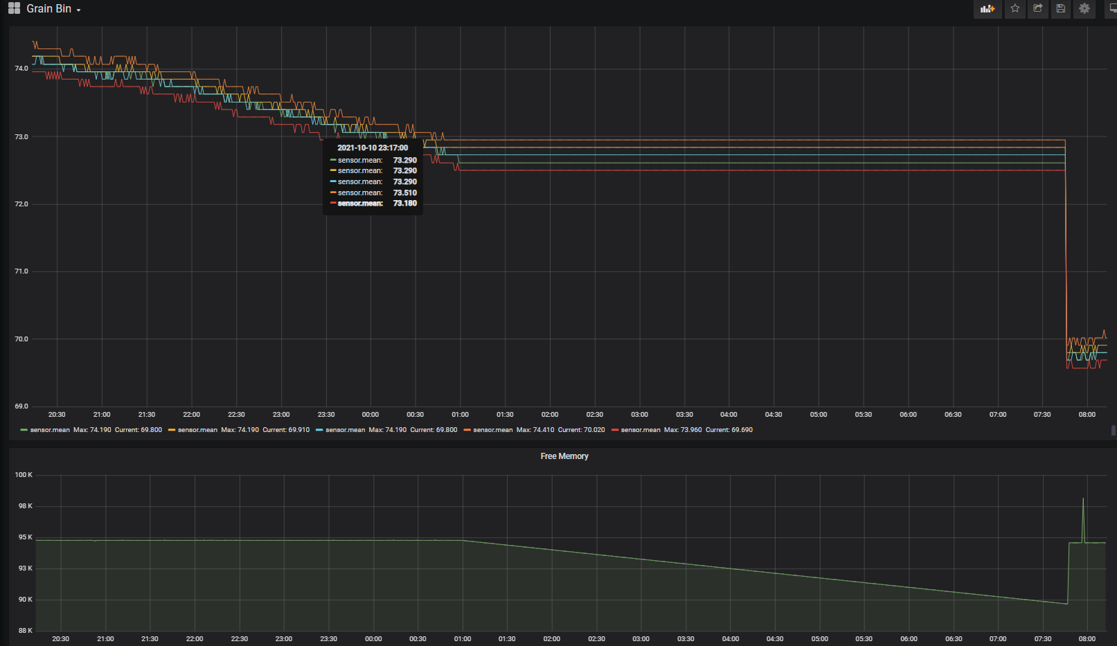
I have started testing the first one currently. I simply commented out the print lines in the loop. Additionally I added a printout of the free memory blocks (as another print-out; cant win them all!) Between these 2 changes and no rewrite of any code, the program has been stable for 3 weeks now which is longer than previously.
I may end up sending the free memory to the cloud to be monitored like the temp data if the future as well.
My next step will be to address the variables within the program. Micropython gives a write up on this, but I do not have a great way to profile memory usage. Hence saving that for a “V3” program.
The mircopython uses addresses to request temp updates, but I am glad you brought that up. Its something I will keep in mind as we move this forward.
As far as hardware goes, the sensors are certainly Amazon fakes. They are powered with a 3 wire 5v,GND, Data setup with a level shifter to feed the ESP32 a 3.3v signal. My plan was to solder red to red, black, to black, and yellow to yellow on a shields 18AWG multistrand shielded wire. This setup using a USB charger was enough to drive the previous 5x DHT22 sensors across 500ft of wire. Hopefully its enough to power the DS12B20’s!
Well, I changed the code last night as above to include a memory logging function. AND shortly there after, it stopped processing/broadcasting WITH almost full and (most importantly) stable free memory. The WebREPL was still functioning. I was able to reboot over-the-air with return to normal function.
NEW PLAN: quick and dirty work around. 1) Have the MQTT server try to restart the device when signal is lost. 2) have the ESP32 reboot if wifi is lost.
Last resort: restart device every 24hrs.
OPI temperature cables just use standard DS18B20 sensors. Their are dozens of examples of how to read them with arduino. Most people are using a 4.7Kohm passive pullup and a single gpio pin. I am using the advanced network driver circuit found on Maxims website but it takes a bit more to get it going. If you want to read moisture cables you are going to have to use either Matt Reimers modified onewire library for the older cables. The new moisture cables use a different sensor and you need a slightly more complicated system. I am going to either build a library or write up some code to read moisture cables and I will post it eventually.
Thought I’d share a setup I’ve been working with. It’s based on Lorawan → TTN → MQTT → NodeRed.
I use a dragino temp/humidity sensor:
The sensor probe is about 4’ deep into the grain.
It’s battery powered and (should) last for years. The device sends messages to my Lorawan gateway. The gateway is configured to talk to The Things Network. From there, TTN sends MQTT messages to NodeRed. Currently, I use NodeRed to select the data I want from the MQTT message and send it to Google sheets (via Form entry) . This gives temp and humidity and then I can calculate equilibrium moisture in Sheets. It updates on a 30 min basis. I can change the update rate, but really no need as things don’t change fast in the bin.
Haven’t ventured into controlling anything, currently just monitoring and manual control.
I’d like to explore using multiple of the SHT31 temp/humidity sensors talking over RS485 into a Lorawan box.
If you want a good way to read multiple SHT31 sensors I would recommend using DS28EA00 onewire sensors acting as a bridge to a SHT31 or SHT35 sensor. Very reliable and compact. They work over extended distances as well out to hundreds of meters. That is how I am doing it and I believe that most commercial cables work that way as well.
This interests me a lot.
I tried to read the temperature with Arduino and a code for DS18B20 and a 4.7kh resistor,
But I can’t read.
I connected an arduino uno to the socket of the stormax box.
Is the polarity correct? If that doesn’t work you should probably try finding another example sketch. Check out m_elias GitHub, I believe he has a sketch on their for a super simple handheld reader.
I wrote a sketch to read live temp, bottom button displays 4 captured min temp. Top button displays 4 captured max temp. I just have never installed on bin. Was going to spread them out on a cable and suspend close to center of bin before filling. Only thing I would like to add is writing to eeprom. I’ve never done that. Min and max resets when powered down. Think it would be better to hold down a reset button for 5 sec. I’m sure your sketch is better than my broken programming. It’s not been tested long term yet. I’ll try to share it tonight when at laptop.
Correction: I didn’t “write” it. It was copied pasted and altered.
The sensors really aren’t to picky usually but the lower the resistance the more current will be available to the sensors and will improve bus stability like what m_alias mentioned. I was running 1000ohm resistors on my setup before it cratered and it seemed to work fine. But if you are just starting out I would try something in the 1500-4700 ohm range and see what works best.