Export RTK-corrected GPS data to RS232 serial port

Refering to that chain:
Satellites—>Reciever+correction(WAAS, RTK,RTX,Omnistar)——> position output data——> guidance / implement rate——> navcontroller ——> Steering output.

Does this mean for AGO that the RTK correction signal goes the way like that:

RTK Base → Internet → Mobile Phone connected w Bluetooth to AOG device → AOG device → F9P / Ardusimple receiver → merged with GPS data → result sent back to AOG?

Then I was wrong, I thought the AOG device is merging the correction data to the received GPS data. Okay, so I need to re-think a few aspects clearly.

Yes you are correct you can route your corrections through AOG to the ardusimple.

Or you can leave AOG out of it go…

Base–>loraradio (or any other data radio)–>Rover(ardusimple or any other F9P variant)
Base–>cellmodem–>internet–>cellmodem–>rover
Base–>internet–>Ntrip–>cellmodem–>rover

Lots of valid ways to skin this cat.

You do not need to use Ntrip if you have your own base, you can use the raw RTCM corrections.

The absolute most accurate setup will be the one with the closest base, and the least link latency, and the least extra data to be sent. Like a local base with a local radio sending RTCM directly.

But cell still works pretty good i was using my friends base 30km SE of me over cellular and I had 1.8" accuracy. If I use the local base in my yard over Lora radio it really holds the line incredibly well. I use Lora because then there is no extra network or caster fees.

But you must send corrections for all constellations you are using in the rover. If the rover is using all constellations, but you only send GPS corrections you will only fix on the available GPS satellites at the rover. The more satellites available to use the more robust your signal will be in challenging territory like hills and trees.

I live in Alberta so I always choose GPS, Galileo, Glonass and Beidou.
QZSS does not help me in any meaningful way its always way too low on the horizon.

Galileo is probably the best system, they have the most accurate clocks onboard, and are heavy into the L5 signal. Currently the most sophisticated satellites civilians can use.
GPS and Glonass are basically Trimble clones of each other, but I see Glonass more frequently with better signal this far north.
Beidou is helpful but if you can only run two or three this one is the one to leave off.

You can use one base for unlimited Rovers.

Can AGOPENGPS export its gps data out over usb to a rs232 adaptor and into my pro 600 monitor? Would be an easy way to have section control while using AGOPENGPS.

Do you need bit rate conversion from the existing AOG input to the output for your pro 600 monitor? If not, why not use a serial port splitter? Don’t like any extra burden for AOG implementation if there is an easy and free alternative already.

I found ttl to rs232 adaptor online. Maybe I could have an output off my uart1 interface on the simplertk2b and then go to my pro 600 that way and skip the agopengps computer. I havent seen anything online about bit rates needed for the pro 600. I have found it needs 9600 baud rate and Nema settings of GGA 1hz

https://www.amazon.ca/Senmod-Serial-Converter-Equipment-Upgrades/dp/B07GYR9D1K/ref=sr_1_5?crid=1BYC2UZ9QSFVA&dchild=1&keywords=ttl+to+rs232&qid=1616548370&refinements=p_85%3A5690392011&rnid=5690384011&rps=1&sprefix=ttl+to+%2Caps%2C199&sr=8-5

1 Like

I got two of these: https://www.ardusimple.com/product/xbee-to-rs232-adapter/

Haven’t tested out yet, but should be able to dump out NMEA from F9P UART, sits on the XBee socket.

1 Like

You can set the baud rate on the Pro 600 input to anything you wish. I have mine set to 38400 baud right now for seeding, currently getting NMEA from my John Deere receiver. One problem is that the GPS coordinate the Pro 600 receives is 30’ in front of the actual drill. Would be nice if AOG could translate the GPS back to the toolbar position (which is already done for on-screen drawing of the toolbar) and then synthesize NMEA for that.

1 Like

Would one of these be able to hook up to the uart and dump out the nema? Little cheaper and I can get it faster haha

https://www.amazon.ca/gp/product/B08QYY8CBC/ref=ppx_yo_dt_b_asin_title_o01_s00?ie=UTF8&psc=1

Yes, that could be wired to the output of the f9p board.

Even something like this,

max 232

Also you can just get the circuit board with no db9 either. Lots of options to go from ttl to 232. You can also get fully isolated ones as well, handy when plugging into strange db9’s.

isolated ttl to 232

Yeah the ardusimple one is an expensive max232, got lazy and picked those on same order with an extra F9P…

Hi PotatoFarmer! I know the post is old but if you can, will appreciate it.

Interested in the “Base–>loraradio (or any other data radio)–>Rover(ardusimple or any other F9P variant)” part of your post. With a micro f9p on a v4.1 board, can I connect an emlid m2 radio? How? Thx

I know you asked PotatoFarmer, I hope he doesn’t mind that I answer, and maybe he’s got more to add?

You can connect your external radio here. Gnd and Sig (your radio’s tx) need to be connected at a minimum. You can also grab 5v or 3.3v power there.

I will play around with the m2 radio using those points on the board. So you think after the physical hook up of the radio, the rtk signal will be served right up to the f9p without doing anything else? Thx.

The RTK destination is to the Teensy by default, the Teensy then routes the data to the F9P. You can use it like that.

If you want to pipe the RTK corrections directly to the F9P you can do that too. See the 3 square pads under RTK Dest? There is a small trace connecting the middle pad to the Teensy (default) pad. Cut that small trace, then use solder to connect to middle pad to the F9P pad.

Those headers and pads are there for the purpose of using an external radio.

Good to know those two options are available. I would surmise if the rtk signal goes to teensy, the normal indicator of achieving rtk correction (one of the three led lights I think) will be expected. If rtk signal is wired directly to the f9p, the led will not light up green but the f9p will nonetheless output corrected gps signal. Thx

I will correct you on that signal.
You get a radio signal from base, and f9p use that signal to calculate RTK, so the led do not care what radio signal or any other signal/message from base station. The led follow the output from F9P single float or rtk.
And if AOG/tablet is connected AOG will show the same, single float or rtk.

By default the RTK correction goes to the Teensy which then passes it along to the F9P. The F9P is always what does the corrections either way. Only the F9P is able to do the corrections.

All the LEDs will function exactly the same using either method.

Hi All!

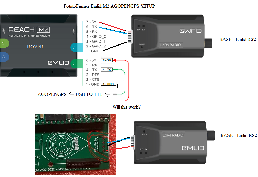
Following up on using an emlid lora radio as source of rtk correction data, as per potatofarmer using a rover with M2 attached to a lora radio and communicating with a base (M2 and lora radio) works. Will the alternative at the rover side work as well with only the lora radio with relevant pinout of ground, 5v and Tx (signal) soldered to the micro4.1 AIO board? Thx.

If I have an RTK NTRIP fix in agopengps how do I send an RTK fixed NMEA string of GGA and GSV from my F9P over UART1 to a MAX3232 to my pro700 monitor? I can get DGPS 12 so far on my pro700 but how do I know or get RTK since I want it for section control. I have also tried the GPS-out app but it doesn’t send the strings I need nor let me select the talker type of GPS only since the pro 700 will only work like that.

The ntrip packet is unpacked by AgIO and the rtcm data is sent to the f9p so it has rtk fix, the nmea sentences coming from the f9p are rtk quality.

I believe the gps_out app outputs “P” (GPS) talker
-4958671079493185013_121
Are you sure you need gsv? Try the latest gps _out from the sk21 GitHub repo.

If you’re using single f9p it’s probably best to use uart2 output to customize the output sentences, baud & update rate. With dual, I think you’re best option is it keep trying gps _out or setup a 3rd f9p.