Flowmeter - RC15 = No flow

Trying to hook up a slurry flowmeter to RC15.

Problem : No flow in RateControl

Everything in RateControl is green and beautiful.

  • Product is green
  • RateControl have speed from AOG
  • Section/work responds when I tap the nozzle in RC.

This is not the correct image, but in the Hz field I get nothing
Also the the calibrating window shows no pulses.

The flowmeter is Freq/Pulese over 24v.
Using a voltage divider I have 10,5v to pin 10 in ampseal.
Everything is grounded in ampseal pin 12

What pins (in module config) should I use?
Are they GPIO pins?


These are the default pins for the RC15. They are GPIO pins.


Is the sensor counts/unit set?

Thanks. Yes. They are set.

Quantity suddenly was 447.5 m3. Not sure when that happened.

Modules:
GPIO pin : 17
Sensor count : 1 - (What is this?

Product:
Counts/unit : 86
Counts/rev : 3
Min hz : 1
Max hz : 3000

Flowmeter:
I can set a few parameters.

I tried adjusting them, but could not see any flow. Until suddenly Qty Applied had increased to 702.6m3.

The flowmeter settings are propably important here.

Hmm.. I can trigger flow now.

The flowmeter has several testmodes. I’ve been running Test Frequency, and set the desired Hz for test. Nothing happened. (But voltage got lower with higher Hz.)

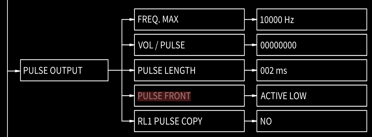
There is a nother selection too : Test pulse output.
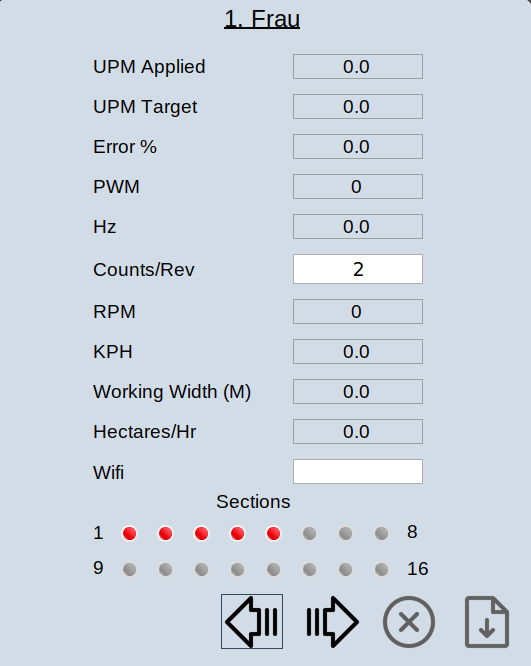
Hitting ok to trigger pulses, the quantity applied increases.

Maybe good enough to get hands dirty for real now.

But would be nice with some comments on the Pulse output settings in flowmeter.

Sensor count is how many flow sensors are used on the module. In this case there is 1 flow sensor used.

1 Like

What kind of sensor is it?

Rpmag from SGM Lectra.

Manual:
Rpmag_T_EN.pdf (2.7 . MB)

What is the expected flow rate and Hz?

between 80-130 m3 pr hour
Hz I don’t know

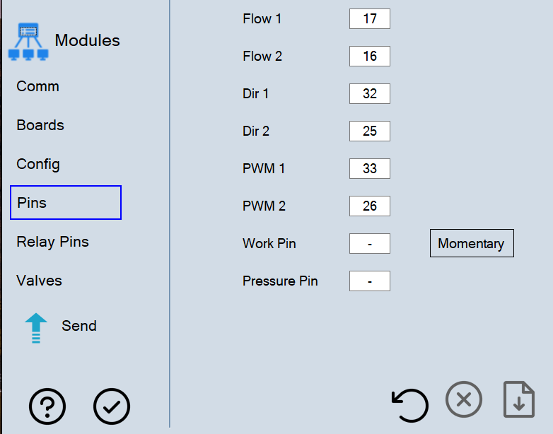
Looks like the sensor has a sinking connection. It sinks the signal when connected to the pcb. RC15 expects a sourcing sensor. It also has 4/20 and modbus. This could work with the RC15 but would require firmware changes. RC11-2 or the RC12-3 would work since they use a sinking connection.

Will it help setting the pulse front to active high instead of low?

I don’t think so.

Did a test in the river.
No flow in RC. Tried active HI and LO.
Also verified with pulse triggering. That generated flow as in testbench.

Claude reccomends to get 5v out of pin 19 in ampseal and run it through a transistor. And let the flowmeter toggle it on/off.

Sounds reasonable to me.

I far from an Hardware expert but just a pull-up on the signal line would do the trick?

@bitfieldfarm

1 Like

Sounds like it would work to me too.

Not sure if I did the pullup correct.
5v out of the RC15 and 4,7 Kohm resistor to signal.

Did not work. Could not trigger flow with pulse test.

Can I use the analog inputs for flow?

It might work with 12V instead of 5V. The sensor and the pcb have common ground?

I think the analog signals would also work. It would take some coding changes.

Tried analog, but no luck.
Long story short : Got an idea to let 8266 read the flow. That worked well.
Then had ClaudeCODE scan the RateControl repo and produce an .ino to simulate flow.

Worked well, then merged the two and have a working setup. And a spare RC15 :wink:

Thanks for all help

1 Like