I have tried the free wheel mod twice now with no luck. I followed along with the video and got it to free wheel but it wont steer when i engage on a line. I have it steering with a standard cytron.
Is there something that im missing or doing wrong?
I have tried the free wheel mod twice now with no luck. I followed along with the video and got it to free wheel but it wont steer when i engage on a line. I have it steering with a standard cytron.
Is there something that im missing or doing wrong?
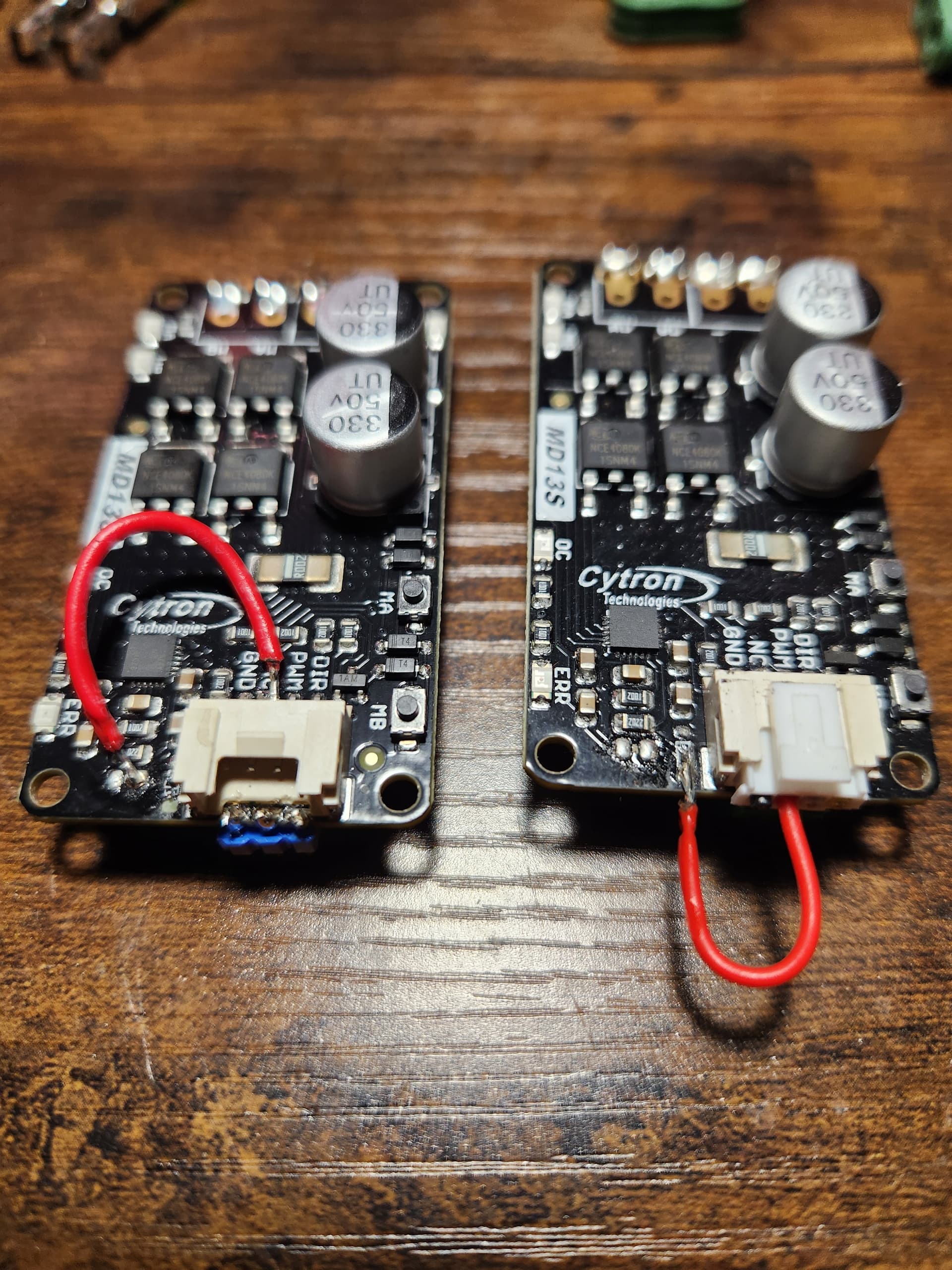
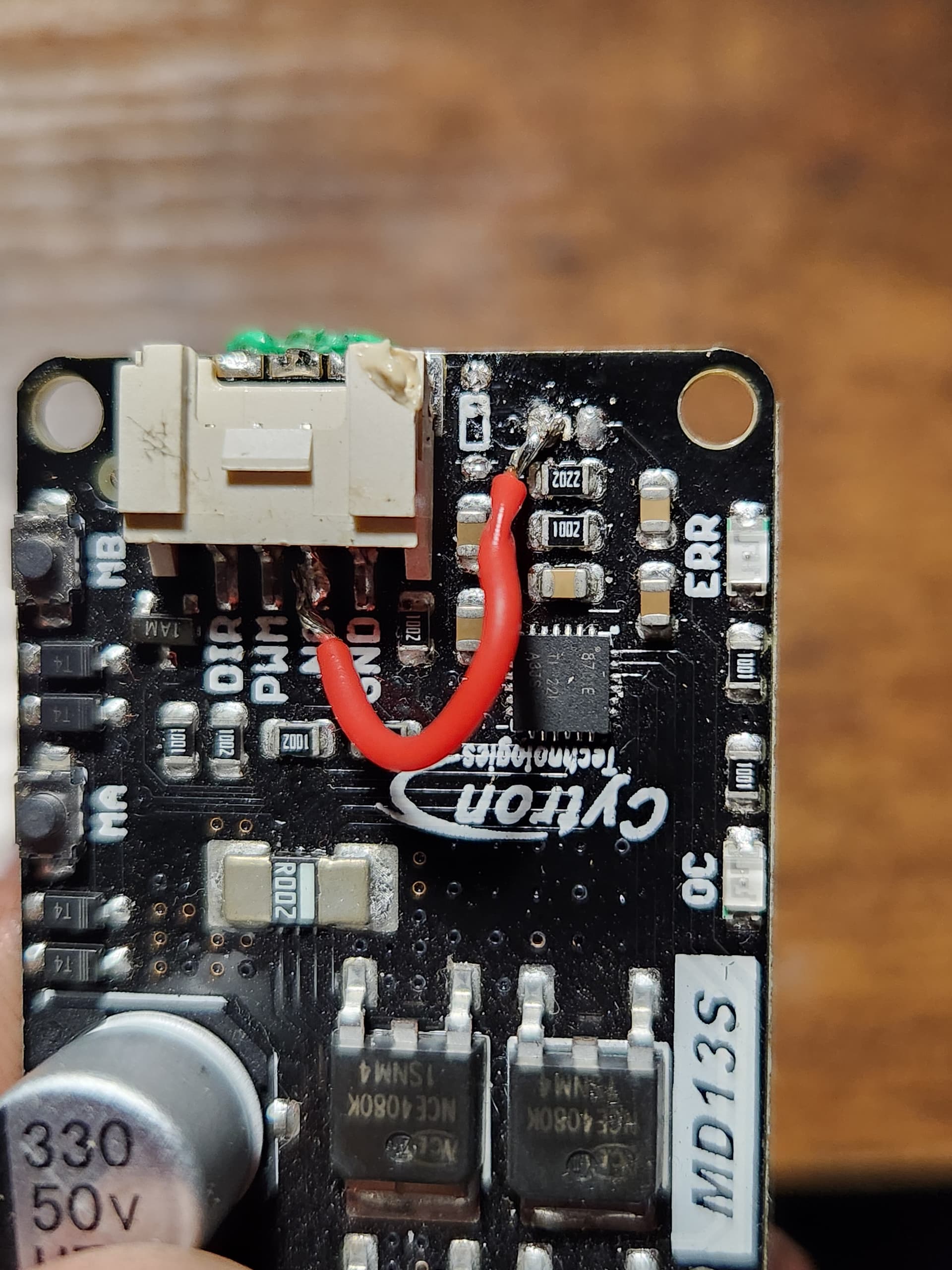
The one on the right is definitely wrong. It needs to look generally like the one on the left. And then you need the wire from the plug to go to the board.
The one on the right was my first attempt and I thought to myself “why I can’t do it like that”. Now I see why I can’t do it like that lol Thanks for the help! I will have to give that a try this weekend.
Good deal. I struggled for 2 weeks trying to figure the same thing out
So i gave the free wheel mod another go and i am still not having any luck. I picked both of the resister things off the board and added the power wire but it will still not steer. System works fine with a unmodified cytron. When i do the free wheel mod, it will send voktage out with the ma and mb buttons but will not steer when i engage on a line. Am i missing a step?
Im not alot of help to you but im sure ive read that when you do the free wheel mod on the cytron you loose the ma mb function so its odd its still working.
Can you use your original unmodified cytron and try the relay mod instead
That setup looks right. With a correctly working freewheel mod the a and b bottoms will only work when autosteer in engaged. I’m not sure if you meant the buttons were working when it was engaged or not.
You might test for continuity from the teensy all the way to where the trace connected to the pad you soldered to goes through to the back of the cytron. And check for shorts as well. Especially where the exposed parts of the wire is close to other components .
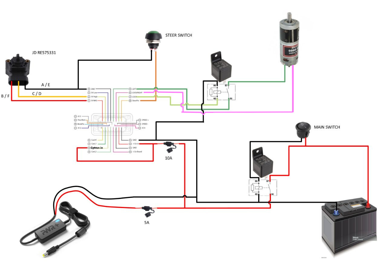
I realize this and old thread, sorry if not in correct place. Looking at the wiring diagram for the free wheel using the Bosch relay it is for a 12V coil which I understand as that is the signal to trip the coil, but if I am boosting my motor to 24V will this relay handle the 24V to the motor or do I need a different relay. The diagram is showing for only using 12V to motor.
Ive used to run this same relay with a phidgets motor running at 24v and seemed ok
You will be fine. The coil is the only load and will need to be 12V but the switch side that closes is just a switch that bridges a piece of metal in the end and it doesn’t really care what voltage goes through it. I have made four harnesses in this fashion for the and all worked fine utilizing the 24v phidgets design.