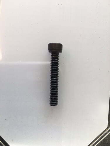
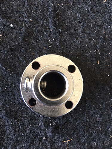
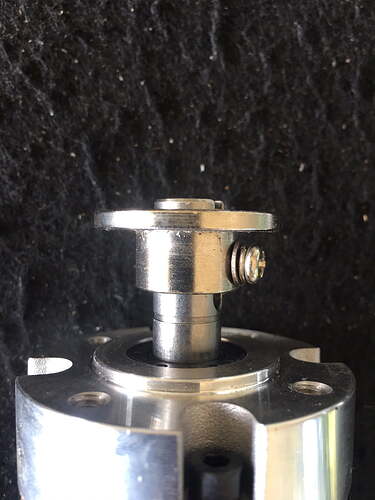
The small screw in place of the set screw is 5/16” long but I’m not sure on the size. Maybe metric. I still used the set screw on opposite side of flange. Lowes or any hardware store should have these screws.
Thanks for all the detail. Will implement your design as soon as my slicks get here.
I’m so lucky I can keep struggling with getting the base F9P board to communicate with the rover F9P till then…yahoo!
Will keep ya posted on my progress.
The motor shaft extends past the flange a little to center the foam wheel as the wheel also has a 12mm hub. It’s only out as far as the snap ring groove but can be adjusted based on your fit.
I’ve yet to get my rtk base rover connection established through an Xbee radio link. I’ve been running auto steer with single satellite link and it has been accurate enough for spreading fertilizer and spraying hay fields.
Just to be clear, my “coding/software expertise” stopped with the simple Arduino IDE for a GPS device my son and I built to tell between which two rows you were in our orchard while spraying in the the middle of the night. He is now doing all the software “adjusting” for this project. Way to many variables for this old farmer.
Thanks again for your clear directions on the friction wheel install.
Nice motor. Are you able to post a link for it please? It looks nice and compact
It’s a phidget 3269 24 volt motor.


