So, I thought I’d write up how I’m getting on with this JD ATU 200. Might help someone out… and maybe someone might know the missing info I’m stuck on.
Was asked if I could get this going with AOG so I thought it would be worth a go. First, a quick look at the bits:
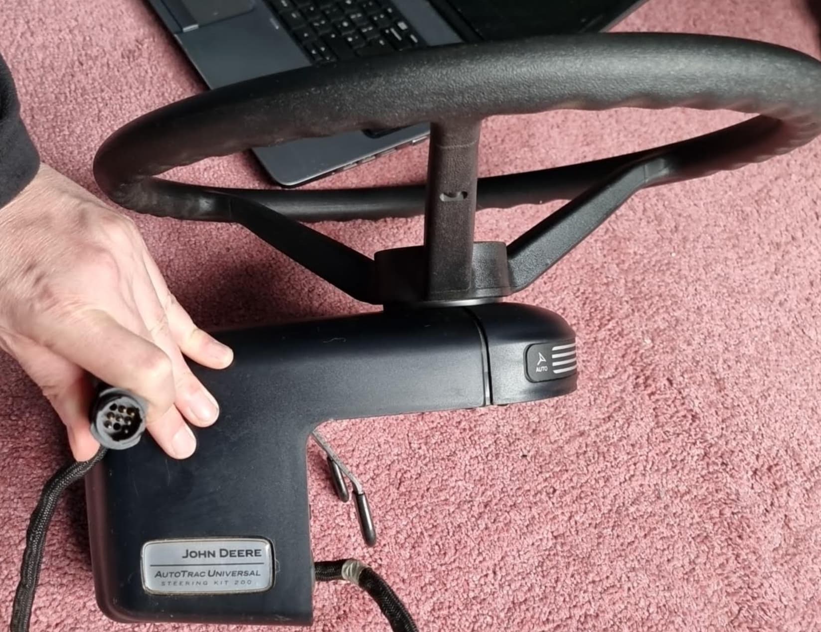

That 9-pin connector is this:
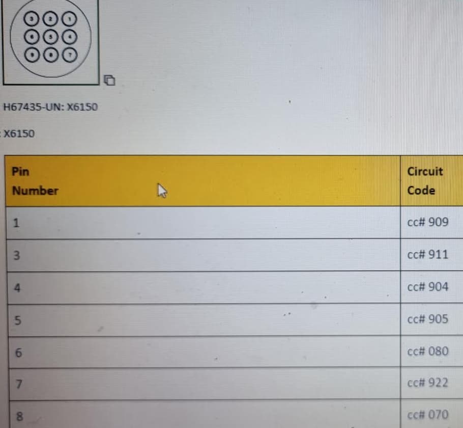
Per the diagram, and as in the cable, only pins 1,3,4,5,6,7 and 8 are present.
According to wiring diagram
- 911 (emergency?
 ) goes to the seat sensor (12v)
 - 904 goes to CAN Hi
- 905 goes to CAN Lo
- 080 not sure yet
- 922 switched 12v power
- 070 Gnd
Raymond pointed me towards this video: https://www.youtube.com/watch?v=jmsdZjLg7Fw
So I already knew it was CANBUS, so this should be relatively easy, right? Power it up, get CanHacker on the case, few code changes… job done?
Hmmmmm… let’s see. Limited data set (because of course things like engine temp aren’t around to mess the output), so that’s good news surely…
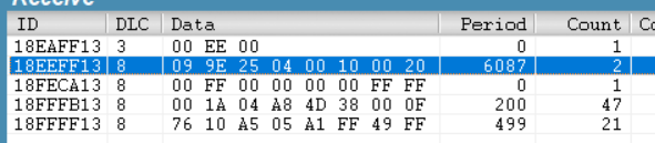
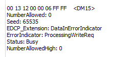
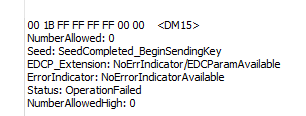
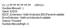
Using csselectronics tool here, I decoded them as:
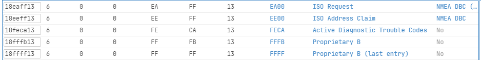
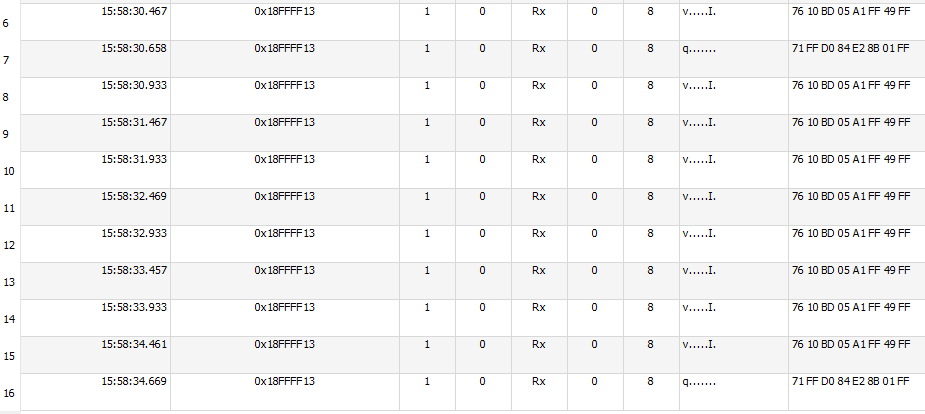
First two are the standard address-claim (steering unit has claimed address 13) and with low counts, we can immediately see which codes we should be focussing on for things like steer angle
Moving the steering wheel, I could see that bytes 4 and 5 of 18FFFB13 appeared to be the wheel position, byte 4 being the minor and byte 5 being the major (little endian, in other words). I also noticed that when I pressed the guidance button on the wheel, the third byte flipped from 04 to 14. Great when there’s such little data around, makes things relatively simple. If I linked 12V to pin 3 at connector, the 04 flipped to 44.
04 - steer ready perhaps?
14 - guidance button pressed
44 - seat alarm triggered
So we can perhaps infer the bitmask here and that would be
  1 | x | ?
  2 | x | ?
  4 | 1 | Ready to steer?
  8 | x | ?
 16 | 1 | Guidance button pressed
 32 | x | ?
 64 | 1 | Seat alarm triggered
128 | x | ?
But… this was the wheel rotation angle tho - this system doesn’t have a wheel angle sensor. So what kind of range does it read? Well, it can be turned infinitely in either direction, and when the scale reads 0, it doesn’t wrap around or anything - it just sits at zero while you carry on spinning the wheel. Likewise, it tops out at 60,000 too and that roughly equates to about 14 turns. If you power it off and back on, it remembers that position, so there must be some sort of re-zero code or something surely, either that or it’ll have to be positioned just right and then fitted which wouldn’t make sense.
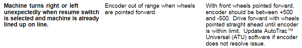
However, from the ATU guide:
Edit: a friend who’s well versed in JD autosteers said:
I do know the steering angle is self calibrating some how, it just does it on the move, no actual calibration function, must be if you drive manually in a straight line for a period of time, or maybe even needs to auto steer on the line to calibrate, not
% sure
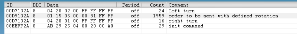
Zooming in on the youtube video, I was able to make this out:
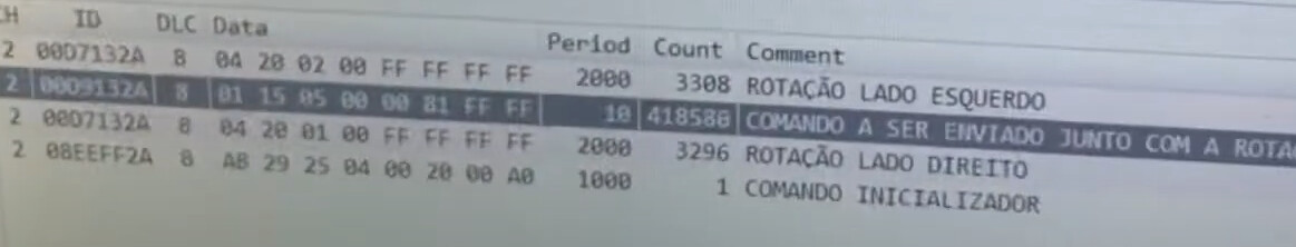
Google translate helped with that from Portuguese:
- Rotate left
- “as order to be sent together with the defined rotation”
- Rotate right
- Init command
And I noted the values as:
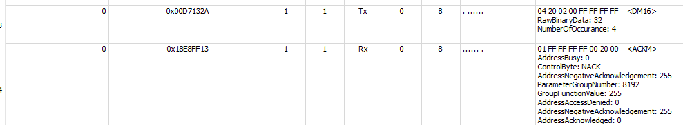
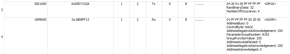
00d7132a 8 04 20 02 00 ff ff ff ff
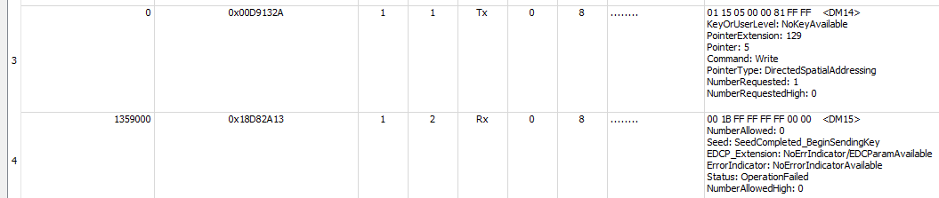
00d9132a 8 01 15 05 00 00 81 ff ff
00d7132a 8 04 2e 01 00 ff ff ff ff
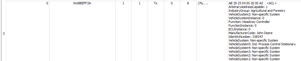
08eeff2a 8 ab 29 25 04 00 20 00 a0
I put the same values into Canhacker and ran it. And the wheel started turning. But in steps and apparently it was random as to whether it would go left or right (possibly as it appeared the left/right lines were being sent approximately the same time, I had thought that script ran top to bottom, but apparently not).
It was at a similar pace to the video above tho…

So, guessing the video author had sniffed those codes from having the monitor attached, but I don’t have that - so very thankful for his video. But, I’ve no idea how to make it turn for longer, turn smoother or faster or anything as yet.
On with more testing - fuzzing the inputs!
First, D7132A
I noticed left turn and right turn are identical PGN with differing data; third byte - 2 for left, 1 for right.
The first byte doesn’t seem to matter and if you increase the 20 to 40, you can narrow the gap between turns so there’s almost none - but it does still stop and start again
D9132A - order
Second byte, it’ll turn with 14, 15 or 16
Third byte - anything other than 5 stops it
Sixth byte - anything other than 81 stops it
8EEFF2A
If the third byte is “OR 16” (fifth bit set), then the motor will run. Otherwise it will not.
Fourth byte will run if 4
And that’s about where I am at the moment. Still trying to figure out why SavvyCAN isn’t playing any more. And I lost a day as I think a dodgy sketch broke Canhacker too.
If anyone spots any huge errors here, please let me know - and likewise if you have any help to add, please do!
I suspect without the terminal I might be stuck, but let’s see how far we get…
Some other notes found:
ATU 200 requires a steady power source with 12.5 V and 4.0 amp while engaged. If there is inadequate current, ATU 200 disengages due to ATU temperature exit code or invalid steering control unit (SSU) voltage exit code.
Activation Criteria:
- To activate system, the following criteria must be met:
- Machine speed is greater than 0.5 km/h (0.3 mph).
- Reverse machine speed is less than 10 km/h (6.0
mph). - In reverse, AutoTrac™ remains activated for 45 seconds. After 45 sec., place machine in a forward gear before reverse activates again.
- Machine is within 45 degrees of desired track.
- Operator is seated.
- Terrain compensation module (TCM) is on.
- Receiver activation required for SF2 or real-time kinematics (RTK).
So, some things to watch out for there. “TCM must be on” sounds a bit ominous…