Hardware hookup/PCB/teensy

Hi everyone, my name is Andrew. I’m a dairy farmer in middle-eastern Ontario Canada. I first found out about Agopengps about 4 years ago at the time the agrabot video was published on Brian’s channel. AgraBot the Autonomous Tractor - YouTube

It was my understanding at the time, that he used an Arduino for the IMU and kinda wired everything together manually. I thought, this is pretty cool, but I don’t have time for it right now, I’ll come back to this later when I have time. (And we bought an outback rebel gps for our sprayer at the time instead)

Since then, we have bought a tile machine and I have become much more familiar with GPS in general. For our tiler I have set up my own RTK base using an F9p from sparkfun and SNIP. As a rover on the machine I use another F9p ( sparkfun RTK surveyor kit) and it works very well with Leferbure design ntrip client app. ( Premium features for grade control).

When I purchased the GPS modules,I remembered AOG, and I bought 2 spare units so that I could use one for tractor guidance experiments in the future.

So now I am at the point where I would like to dive into Agopengps. I have a Panasonic toughbook CF-31 already. But it seems like the state of the “system” is in an entirely different place where it was the last time I was here.

I realize this is a community project and the documentation on community projects is often not the greatest. I would really like to figure out what is going on here, without having to read back the last 6 years of history in development of the software and hardware.

So I’ll try and guess at what is going on and maybe someone can point out my misconceptions or poor assumptions.

Firstly, it seems that the microcontroller has evolved from an 8bit Arduino to a teensy 4.1, in order to use the Ethernet port to communicate with the PC. ( Is the Arduino/serial method no longer supported?).

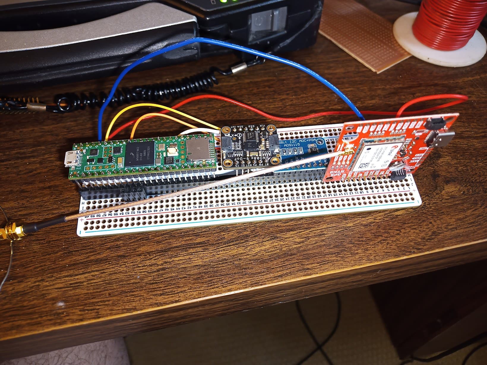
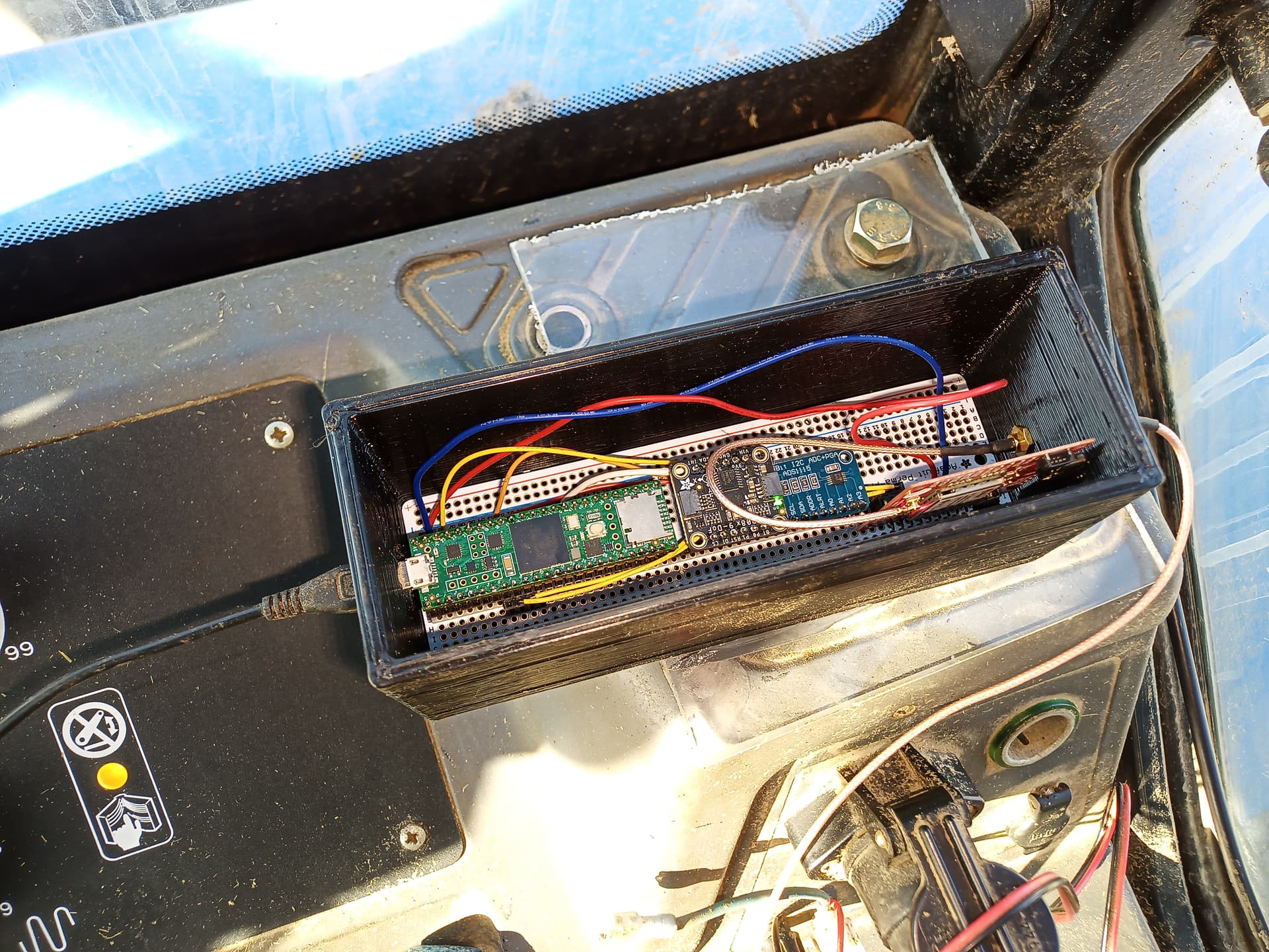
Second. I see a lot of mentions of “the PCB” including all the relevant files to order one. I haven’t dug in and actually looked at the Gerbers. But what I am surmising is “the PCB” provides a place to plug in the IMU, the gps module (or two) and the microcontroller. Maybe provides a power supply too? It seems to me the “standards” PCB expects the ardusimple F9P board, so my sparkfun F9P would not slot in. I suppose wheel angle sensor also would plug into the PCB somewhere.

Third, the community has settled on one specific IMU module from adafruit.? I’m not sure which one it is, but I’m pretty sure I don’t have it. I do have an MPU6050 though, which I think maybe the original project used?

So, if I wanted to get started with Agopengps today, knowing the GPS I have is not the one that is expected, is it still worth getting the standard PCB? Can I wire this up on a breadboard? Is atmega hardware still supported?( I have a lot of Arduinos, no teensy) (or maybe ESP32?)

If I do buy a teensy, is there documentation of what needs to go to each pin, or do I have to reverse engineer the Gerbers ? (And which IMU do I need, or will my 6050 work)

Sorry for the long post, just trying to get my bearings here, I’ve been powered off so long my magnometer needs calibrated, some might say.

Cheers, and thanks for making so much progress in capability while I wasn’t looking. But curse you for making it so complicated! (Kidding)

The Teensy was adopted more so because it is faster and less so because of native ethernet. The extra speed is required for PANDA, which is a method of synchronizing IMU measurements with GPS measurements. Better measurements = straighter lines.

The Arduino is till supported. The Arduino can also use ethernet with an ethernet shield.

Its called the “All in One” PCB, or AIO for short. There’s 4 versions. Two version have the ArduSimple RTK2B footprint, and the other 2 versions (Micro) use the ArduSimple RTK2B Micro footprint. Each of those has a Deutsch and Ampseal variant.

You are correct that your SparkFun F9P will not slot in. You can still use your Sparkfun F9P, but you’ll probably be gluing it to the PCB and running some wires to the right spots. It would be very doable.

The AOI boards use one big IO connector, either Deutsch or Ampseal. Power and wheel angle sensor and all other connections are made through that connector. You’ll want to use Ampseal as it has more pins than the Deutsch and the Deutsch is already showing signs of being limited.

The BNO085 is the current crowd favourite. It’d be worth buying even if you already have MPU6050. I’m not sure if the AOI boards support the MPU6050, they do support the CMPS14.

In order to use PANDA you need a Teensy, everyone says PANDA is worth it (I haven’t tried both). You can’t create PANDA using an Arduino.

If I were in your shoes I’d build AIO boards. Either hot glue/wire your Sparkfun F9P’s in place, or create a small PCB to adapt them to the RTK2B footprint. Buy new IMUs, BNO085. You can order the boards mostly assembled/soldered. I would not put a breadboard in a tractor.

2 Likes

Thank you very much for the info! I am on board with picking up a teensy and a BNO. I think I understand the PCB situation… I guess I am going to have to dig into the gerbers to see what wires go where. I’m not a fan of Deutsch or Ampseal connectors, and I think I’m even less of a fan of the “one wiring harness” philisophy, but I understand why the community has gone that way. I’m pretty sure thats how the commercial similar products work.

I am a fan of the circular “avation” type connector (gx12) and think what I would prefer to do is 3d print my own enclosure and wire up everything that needs to leave the box into that type of connector, since i already have a lot of them. I guess that is the upside of an opensource project.
I could likely run the wires from the traces for the ampseal, to the GX pins with flying leads similar to the proposed method for wiring the sparkfun f9P?

Couple new questions. When you said buy new IMUs… do I need more than one?

and regarding breadboards, I don’t mean a solderless one. I mean a soldered one. That is how this project bagan isn’t it?

Next, regarding the connection topography/block diagram. I saw another website describing how it works but I think it may have been innacurate or outdated. They had an MCU for WAS/IMU/steering control, plugged into the pc, and the GPS module also plugged into the pc, and another MCU for aux out(section control) all via serial(usb)

In the modern usage, does the GPS plug directly to the PC, or are the GPS and IMU data signals “wrangled” by the teensy(is this perhaps what PANDA is?) If not, I could plug my F9P into my computer.
It would be very helpful to have a block diagram with arrows describing signal flow and connection, methods (phy and proto) and it would look really nice in the docs too. If sucha thing already exists, or if different versions exist for all the supported configurations I’d love to see it/them.

If they don’t exist… Once I have muddled through how the system functions I’d be happy to do up the diagrams, and write some new documentation for what component does what and how, and what the different options are.

You only need 1 IMU.

With serial com you will have to plug the GPS into the computer. The Arduino ready the WAS (wheel angle sensor), IMU, steering cutout, work switch, drives the motor/valve etc. Typically you can get by with 2 serial cords.

With the Teensy you only need one connection to the computer. The teensy takes care of everything else.

That’s the general idea.

Yup, you could do that.

Just one per tractor. Or zero per tractor if you want to use a dual GPS setup.

The AIO boards are a four layer board. I’d be concerned at the number of wires required to use a soldered breadboard (protoboard, perfboard) for full functionality. But yes, technically it can be done that way. It would be a lot more doable if you can remove sections of the board like the CANBUS or Danfoss components.

That would be a diagram for a non-AIO board, like an Arduino based board.

GPS fixes occur 10x a second, IMU measurements happen more than that, the GPS and IMU are not synced in any way. The most accurate way to combine the data is to have some fast device connected to both the GPS and IMU and try to synchronize the measurements, that’s what PANDA is and it happens on a Teensy.

On the AIO boards, the GPS and IMU are on the board connected to the Teensy, the Teensy makes PANDA and does everything else like autosteer too.

On the Arduino boards there’s different ways of doing it. Most (all?) of the boards have an IMU, and the GPS is connected to the computer. The measurements are not synchronized. That’s how it would have been a few years ago. The other way “modern” is to remove the IMU from the Arduino board, create a new circuit with the GPS, a Teensy, and the IMU, and let that Teensy create PANDA. The arduino handles all the autosteer stuff.

3 Likes

All I need right now is guidance, and I suppose I would want later a wire for left and a wire for right. Hydraulic steering seems the best option given my old tractors. It would take a lot of engineering to make a friction wheel or a gear.

So I could delete anything from an AIO design that would have anything to do with isobus, or section control or even the drivers to run the wheel motor.

I guess I really should look into the design to see how many wires I’m dealing with, but it doesn’t seem to me that wiring a teensy to a gps module, wheel angle sensor and an IMU would be prohibitive to do manually.
It should be 4 wires for each, max, right?

you don’t need wheel angle sensor.

So it’s just teensy + GPS +IMU → 10 wires or so?

It really wasn’t that hard to hook up.
I haven’t wired the ADC yet, but I also don’t have it in the tractor yet either.

When I move the board around, I see numbers changing in the serial monitor, so my BNO I working… I think?
Next step, hook up a GPS antenna and plug into a computer running “the software”

1 Like