At the beginning of the code there is an explanation, so section 0-5, D7-D12, so I think section 1 is D7.
/*
* This program only turns the relays for section control
* On and Off. Connect to the Relay Port in AgOpenGPS
*
* Hydraulic Raise D4
* Hydraulic Lower D3
*
* Tram Right Side D5
* Tram left Side D6
*
* Section 0 to 5 – D7 to D12
*
*/
Don’t know why I couldn’t get my led to blink, got it working so I could test and understand.
So the .INO with the defaults works as presented. If you use it as default, pin 13 will be your left most relay, pin 5 would be 2nd and so on. Pin 4 would be relay 10.
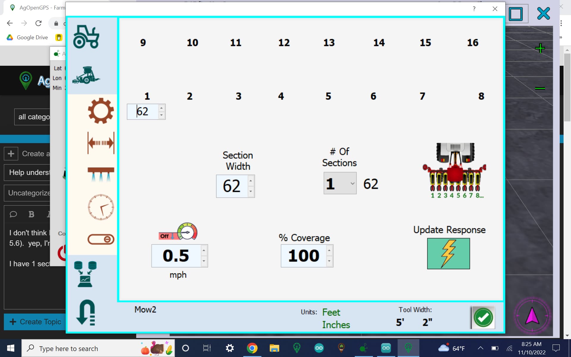
So in my case with 1 section;
if (pin[0]) - I have setup 1 section so we are going to set -
digitalWrite(13, - arduino pin 13 to the value read in -
relayState[pin[0] - 1]);
This makes it pretty easy to set the relay pins to what ever you want, just change the pin # to what you want.
Section 1 = 0 in the nano, because thats where the nano starts counting.
But then is addressed to a pin on the nano, In the stock .ino they seem fairly random. When I get back to the laptop I will post the udp .ino I have with really good notes in it.
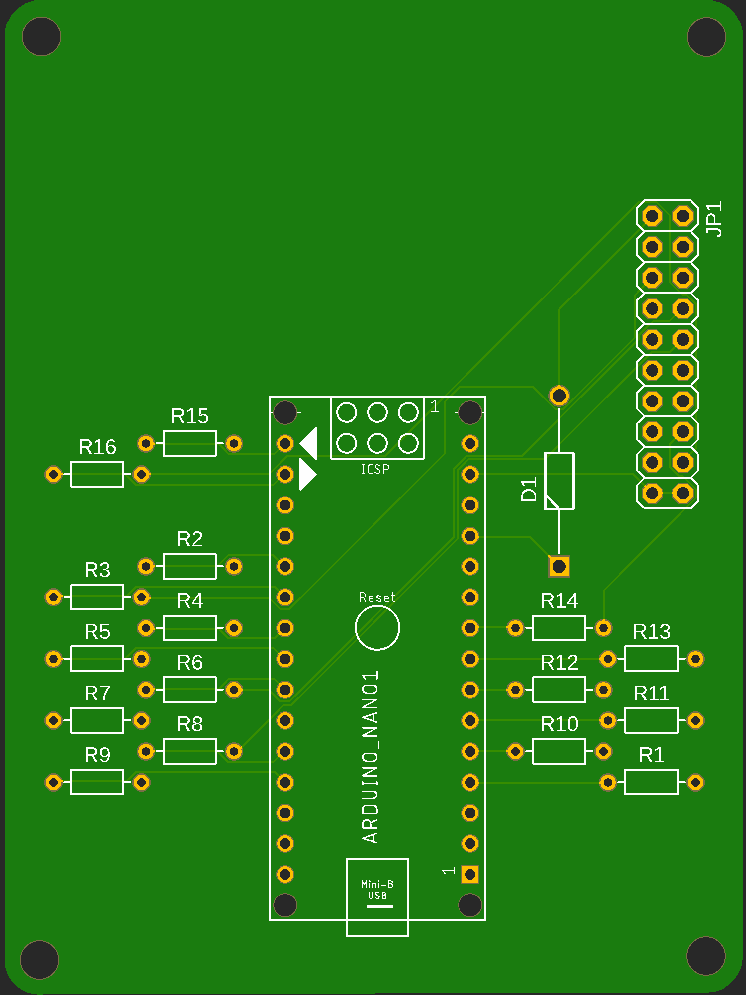
The cards from jlcpcb are at customs so soon will be testing easy section control hookup.
On telegram Brian has added 64 equal size sections, but it will not affect the current setup.
The output configuration is meant to work with a PCB to directly connect to this preassembled relay board, in its 12 V variety as it comes with a 5V regulated supply