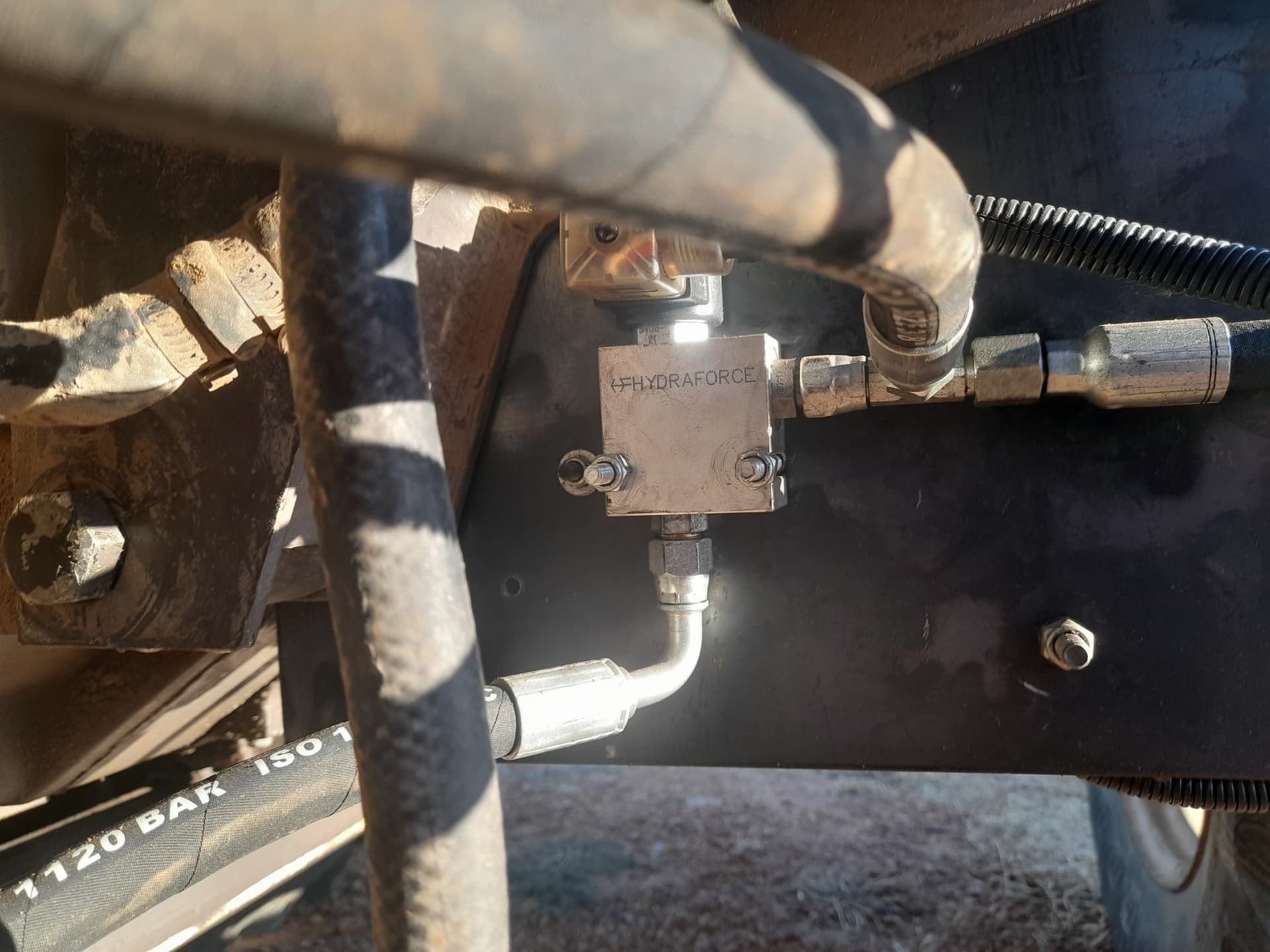
Finally had some success plumbing a hydraulic valve into my Open Centre LS orbital.
I’m using the Hydraforce SP10-57C with a 6/2 valve.
The 6/2 valve by default allows the orbital to connect to the steering ram but when powered up blocks flow between the orbital while allowing the hydraulic valve to flow to the ram.
I have the steering working when manually providing power to the solenoids.
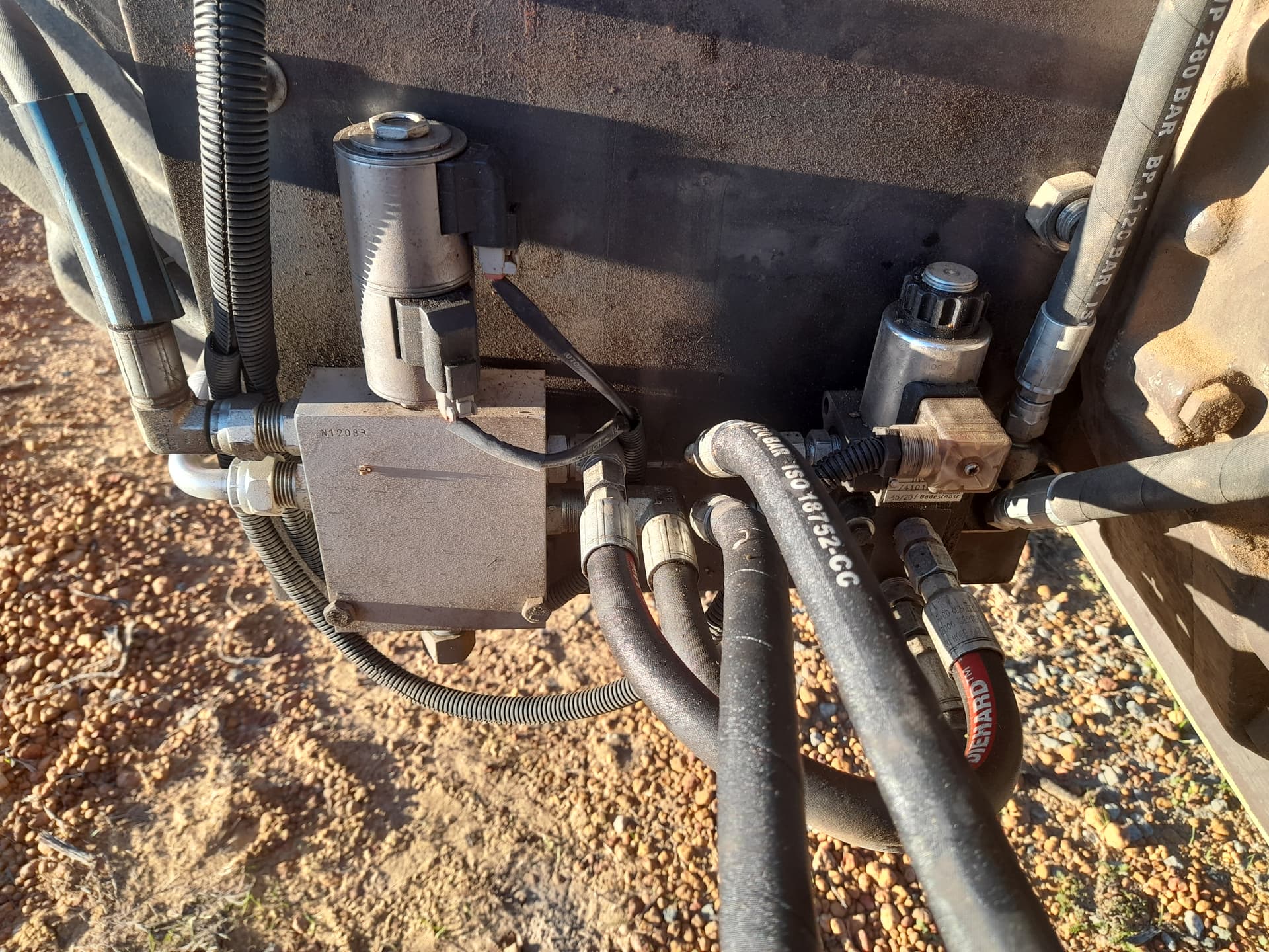
I’m now in the midst of mounting everything neatly, both under the bonnet and inside the cab.
Have a question re power to the 6/2 solenoid. I have found a few threads but not being anything remotely like an electronics person can someone point me in the right direction?
How do I wire it in? What do I need? I’m using on old PCB (doesn’t have a version written on it, but I’ve had it over 12 months) with a Cytron motor driver installed.
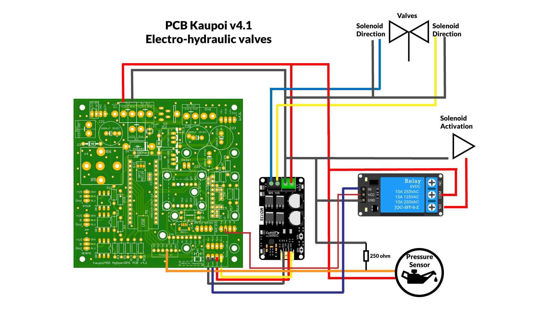
For the 6/2 valve using a Cytron you can simply activate a relay from the D9 pin (PWM2 on the board).
I don’t know if the old boards had it, probably since it is needed to feed an IBT.
for the relay you can use something like this: gravity-single-relay-module
Wirring:
Control side(the supplied cable) simply to PCB ground, +5v and pin D9(PWM2)
Load Side (terminal bloc) you feed 12v to commun and the selenoid positive to NO.
I am not an expert on theses relay but I think some (like this one) use a 5v(high) signal and others use a ground(LOW) signal.
A 5v(high) signal is better (and safer) as it will only engage if there is 5v from the arduino.
Been trying to get a million other projects finsihed and have finally gotten around to mounting the valves neatly.
I’m using a valve to cut off flow to the orbital and send it to the Hydraforce SP08-57c and a 6/2 valve to stop leaking from the steering ram back through the orbital.
It all tested ok when I had it mocked up and manually connected wiring to a battery.
I have upgraded to AgOpenGPS 5.5. What an awesome looking product.
Haven’t got it working with the PCB (Version 1 board) yet as I think I may have made a faulty connection to the Audrino Relay I am using to turn the 6/2 valve on.
I have followed this wiring diagram and the advice from Pat above:
Its working - sort of. Found a bad connection on one of my valves and to my steering switch.
It now activates but steering currently does not work. If I push the MA and MB buttons on the Cytron board the wheels steer left and right but not while using AgOpenGPS. When AgOpenGPS is activated one of the LEDs on the Cytron (either MA or MB - cant remember) lights up but the tractor would still maintain what ever line I steered it on and did not lock onto the AB line I have set.
I am running AgOpenGPS 5.5 and have uploaded the lastest INO found in the support files.
Do your wheel turn? when agopen gps is active? And make a picture of your settings. Where you need to save to arduino. steeringbutton, cytron etc…
I use the PCPv2 version and only use 3 wires black, white and yellow from cytron. Only had once that i changed pwm1 and pwm2 and kept on steering one side.
Ok. I seem to be getting somewhere with it. Some crude testing with it and the tractor attempts to track an AB line.
So confirming that all the wiring and hydraulic valves are working I restarted the configuration.
Following Brian’s Basic Steer Settings YouTube video I confirmed that my WAS matched my steering wheel - ie when I turned the steering wheel left, the green bar went to the left and when I turned the wheel right the green bar went right. I then zeroed the WAS.
Next, opening the Steering configuration box more I performed a right hand semi circle. Pressing the record button and driving a semi circle, the screen said - Drive Steady and measured the semi circle. One completing the semi circle I pressed the stop button and the diameter was measured but the Steer Angle was 0.
WAS is zero. Its when trying to fine tune it I am having a problem. Perform a right hand semi circle and the diameter gets measured but the angle does not. Just shows 0 degrees.
Thanks to @Raycorp for his assistance on getting my settings tuned.
Considering I’m using an AB line across a paddock which is extremely bumpy from the one way plough and have no corrections I’m very impressed with how AGOpenGPS works.
Getting a pretty straight line despite all the bumps and the paddock is levelling out nicely.
Even sent my former boss a video of the set up turning around at the end - a feature he doesn’t have on his system.
Unfortunately the 5v relay which turns my 6/2 valve on stopped working late this afternoon so I’ve had to stop. A quick trip to the city in the morning (150km each way) and I’ll be up and running again.
I’m not sure what the trouble with your really is but you might want to make sure you have a diode across your 6/2 coil to protect the relay contacts. Without a diode the relay contacts arc and stop making contact when operated.
I had same problem with my enablers controlled directly with a chinees 5v relay. Enables take more then 1 amp. I now let 5v relay switch a 12 relay and the 12v relay controlls enablers.
No problems anymore…
Well that was before complet system was stolen by gps thiefs.
Been happily using AgOpenGPS for the last few days scarifying my extremely bumpy ploughed up paddock.
It copes pretty well across the bumps and to make sure I got complete coverage I set the implement width narrower than it physically is.
Today I tethered my phone to my laptop, configured NTRIP and entered the correct width of the implement. Did a run, turned around and did the next run. Nice straight lines with minimal overlap and I think that was caused by me only measuring from shank to shank and not taking into consideration the width of the point.