Hi there. I want to steer a tracked vehicle which is driven by two independent hydraulic motors, each driven by its own pump. Steering and direction is achieved by two independent levers in the cab. The levers vary the voltage and polarity from 0-12 volts to drive control valves mounted on each pump. My thought was that direction and speed can be controlled manually by the right-hand lever, the left-hand lever is overridden by the autosteer, which would slow down or speed up the LH track to steer.
My question is- How do I go about it? Has someone done something similar before? Thanks.
Do you want autosteer to work in reverse as well as forward, or is forward operation only ok? How nimble/sluggish is the vehicle? What is it? A dozer or a snowmobile trail groomer? Do the joysticks stay in position when you let go of them, or do they return to center when you let go? Do you vary the speed constantly with the joysticks, or do you just set a cruise speed?
Are the joysticks Hall effect or potentiometers or other? Are the signals easy to intercept? Will the machine error out if joystick signal is momentarily lost (if you were to switch the joystick signal through a relay to some other signal)?
I think the cleanest solution (not the least amount of work solution at all) is to create a pcb with a micro controller, adc, dac, communication to AoG, and maybe some switch inputs. The PCB connects between the joysticks and the rest of the machine. The joystick inputs are read at all times.
When not in autosteer mode, the dac outputs are set to match the joystick inputs 1:1. So even though it’s technically the microcontroller that’s driving the machine now, as an operator the system would seem unmodified when not in autosteer mode.
When in autosteer mode the dac’s are varied to steer the machine. The joystick is still being monitored and you can read joystick action and use it to disable autosteer and return to manual mode. The steer angle from AoG just becomes a voltage difference multiplier value. You don’t need a wheel angle sensor or any complex math there.
How the travel speed is set during autosteer mode is a bit undefined, there’s a few options. You could use the joystick position at the moment that you engage autosteer. You could use the average joystick positions as the travel speed and only disengage when the joysticks command a turn past some threshold. You could use an additional dial or lever as the cruise speed. Disengaging autosteer might cause abrupt stops of the machine depending on how your joysticks work, but you could program a gradual deceleration.
I think that would be the Cadillac solution, lots of flexibility to make it work across different systems. Would need some more info to come up with the base model Ford Ranger solution.
Thanks for your reply. The vehicle is a harvester. The autosteer only needs to work in the forward direction. The powertrain is quite responsive and will react to small movements of the joysticks. The joysticks remain where they are set if the operator lets go of them and they are continually adjusted for steering and speed control. The joystick output voltage is varied from a potentiometer in parallel to a voltage divider. The track speeds are slightly offset so one track will spin faster in each direction, ie the LH track is faster going forwards and the RH track is faster in reverse. This is so the vehicle can still have steering at maximum speed in both directions. Going forward, the machine speed is set by the RH joystick because it is the slowest, and left is used for steering.
My thought was that the RH joystick sets the machine speed and remains unmodified. The LH joystick output is passed through a changeover relay. In normal operation the LH joystick controls the pump directly. The autosteer will be activated by a switch which turns the relay on. The autosteer would simply need to vary the voltage to slow down or speed up the LH track to maintain the desired direction. If the machine needs to speed up or slow down, the operator will adjust the position of the RH joystick and the autosteer would slow down or speed the LH track to maintain the direction. To turn the autosteer off, both joysticks could be returned to the neutral position and use the neutral switch to turn the relay off. This way, the autosteer can’t be turned off while in motion which would lead to a loss of steering control.
As far as design goes, I’m looking for simplicity and therefore reliability. These machines have no electronics other than an ECU just for the engine, so I don’t have to integrate anything. The only other problem I have is a steering angle input. I was thinking about having an Arduino monitor the track speeds and compare the difference, then use the result to output a 0-5V signal similar to a WAS on a tractor.
I think a system like that would steer anytime that you make a speed adjustment with the RH joystick, and it would take time for the LH side to correct. The system’s integral term would be making the adjustment, and it wouldn’t make an adjustment until you are off track. Monitoring the RH joystick voltage with the microcontroller would allow the system to adjust the LH side instantly.
Are the joystick’s outputs +12v to -12v? +12v is full speed ahead, 0v is stop, -12v is full speed reverse?
The joystick’s outputs, they are +12v to -12v? +12v is full speed ahead, 0v is stop, -12v is full speed reverse? Each joystick just has one output signal wire? And you said the system is “dumb,” so it’s not going to fault out because it momentarily lost signal when switching signals with a relay right?
If all the above are true then I have a different proposed solution. The solution is maybe kind of kludgey but the solution will allow you to use a regular all in one AoG autosteer board with unmodified code.
Instead of changing over only the LH joystick with a relay, changeover both the RH and LH joysticks with relays.
Changeover to a new tracked vehicle control circuit that you will have to make. The new circuit consists of two potentiometers. One potentiometer is forward/reverse (or only forward speed), the second potentiometer is steering.
Make yourself a nice handle or something for the forward/reserve potentiometer, that’s what you’ll be setting your speed with during autosteer operation.
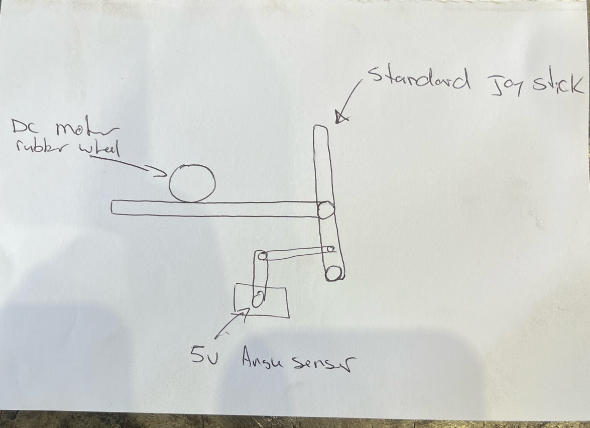
Connect the steering potentiometer to a small DC gearmotor and a WAS sensor (potentiometer). Connect the DC gearmotor and WAS sensor as normal.
Add a 5v angle sensor to both drive handles so you can get the difference between them.
Make a small DC high reduction gear motor with a rubber wheel driving on a rod to pull/push the drive handle.
You can manually move the handle at any time the rubber will just slip and cut autosteer off. And the auto steer will start from where you left the manual set position.
Depends if your more into a mechanical design or electrical design I guess.