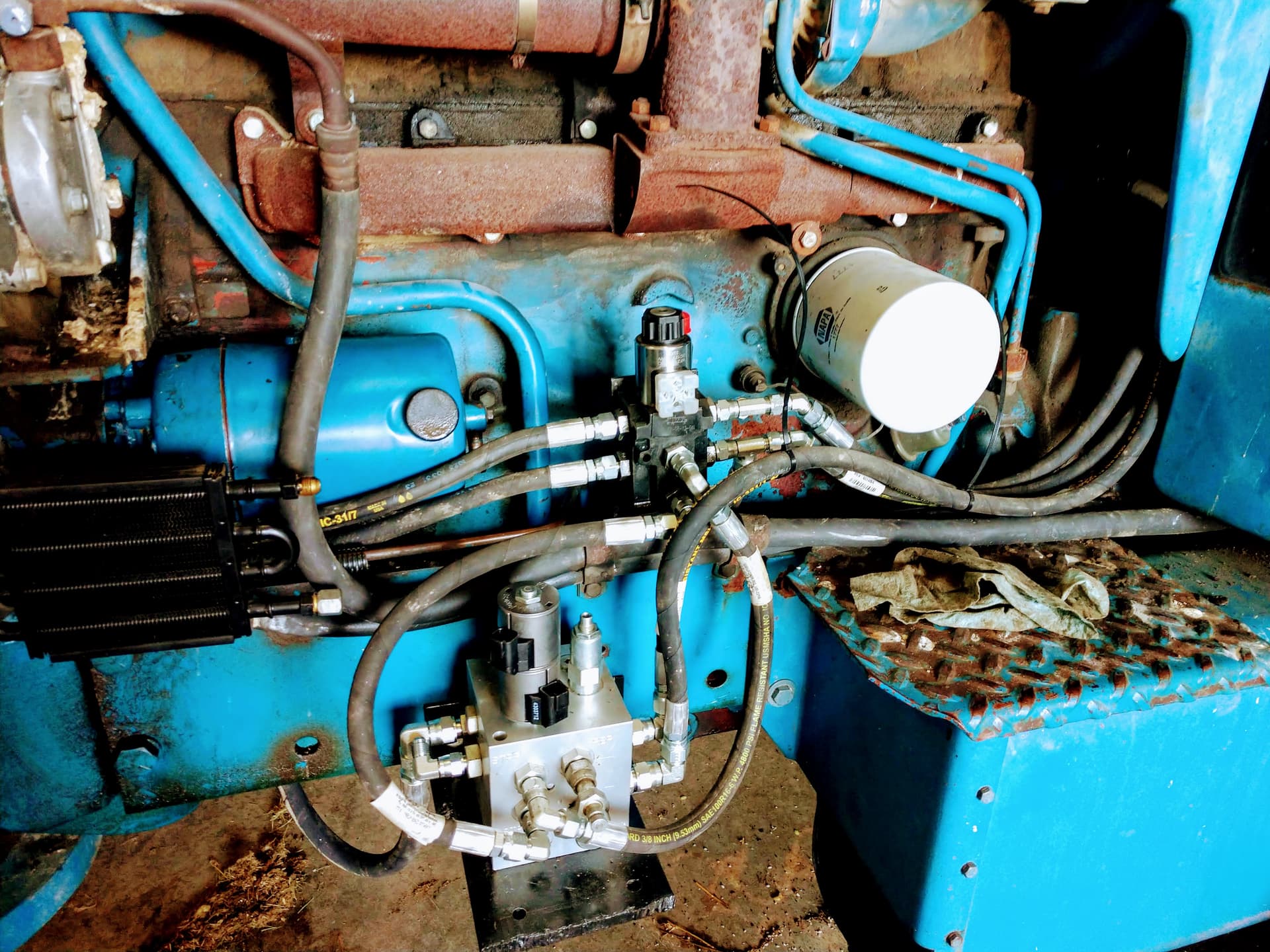
We have this hydraulic valve that we bought off ebay. It had been dropped and the PWM spool was bent. We received it and checked the internal design. It was what I thought it was, an autosteer valve. I’m trying to track down what company this valve was manufactured for. In the meantime we have this installed on one of our tractors.
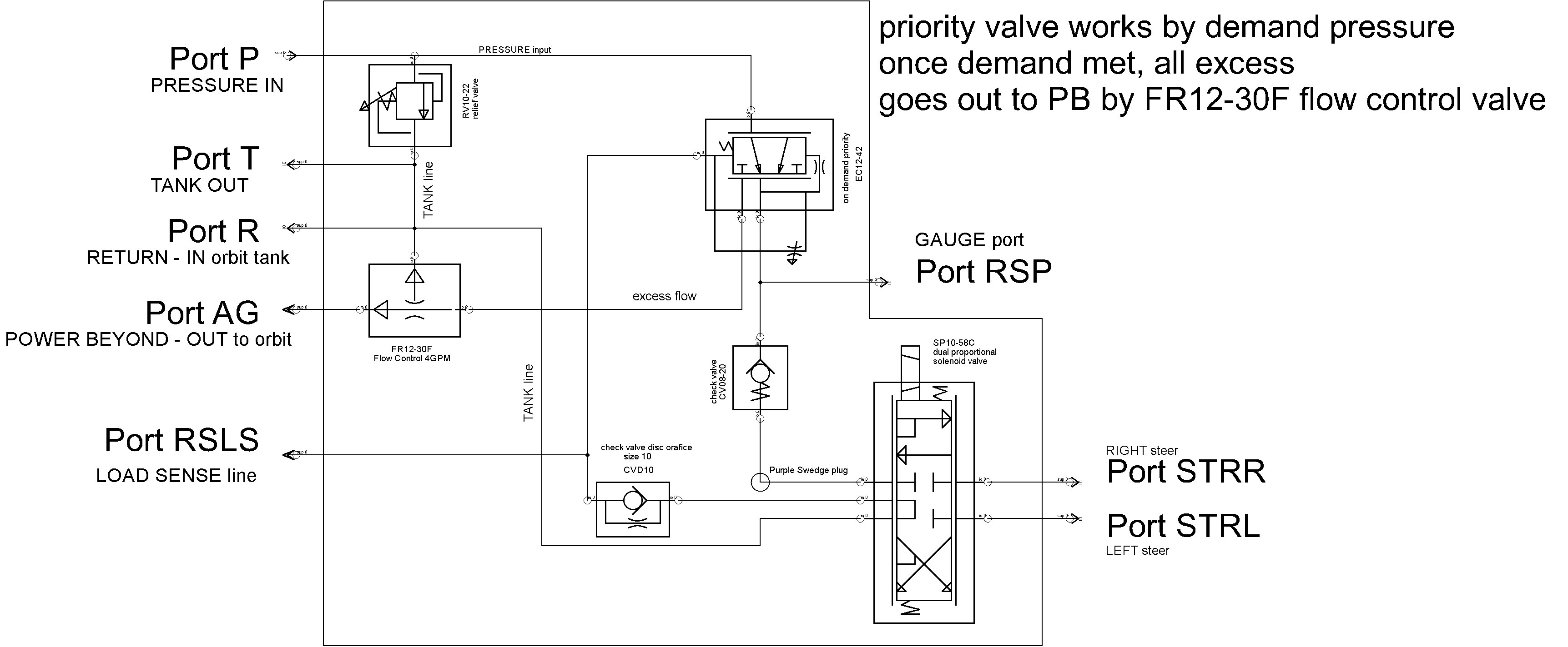
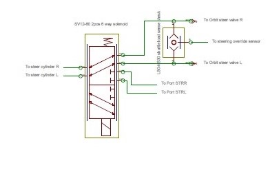
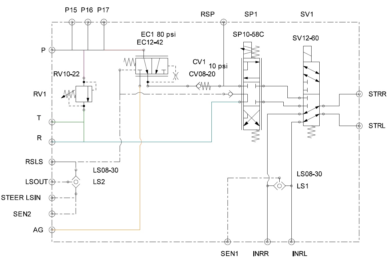
The valve is designed with a pressure demand priority spool so it works on open center systems. It has an internal Load Sense to activate the priority spool so it can also be used as a closed center valve. We had to add a dual circuit 6 port valve external to cut off the orbit steer valve and installed a check Tee and pressure sensor there for the manual override signal.
component list:
RV10-22 relief
EC12-42 priority in block LS activated
CV08-20 check valve
SP10-58C dual proportional valve
CVD10 check valve orifice added to the SP10-58C bore (optional add to SP10 as Hydraforce design option)
FR12-30 4gpm flow control (not needed really as this tractor is a 4.1gpm pump)
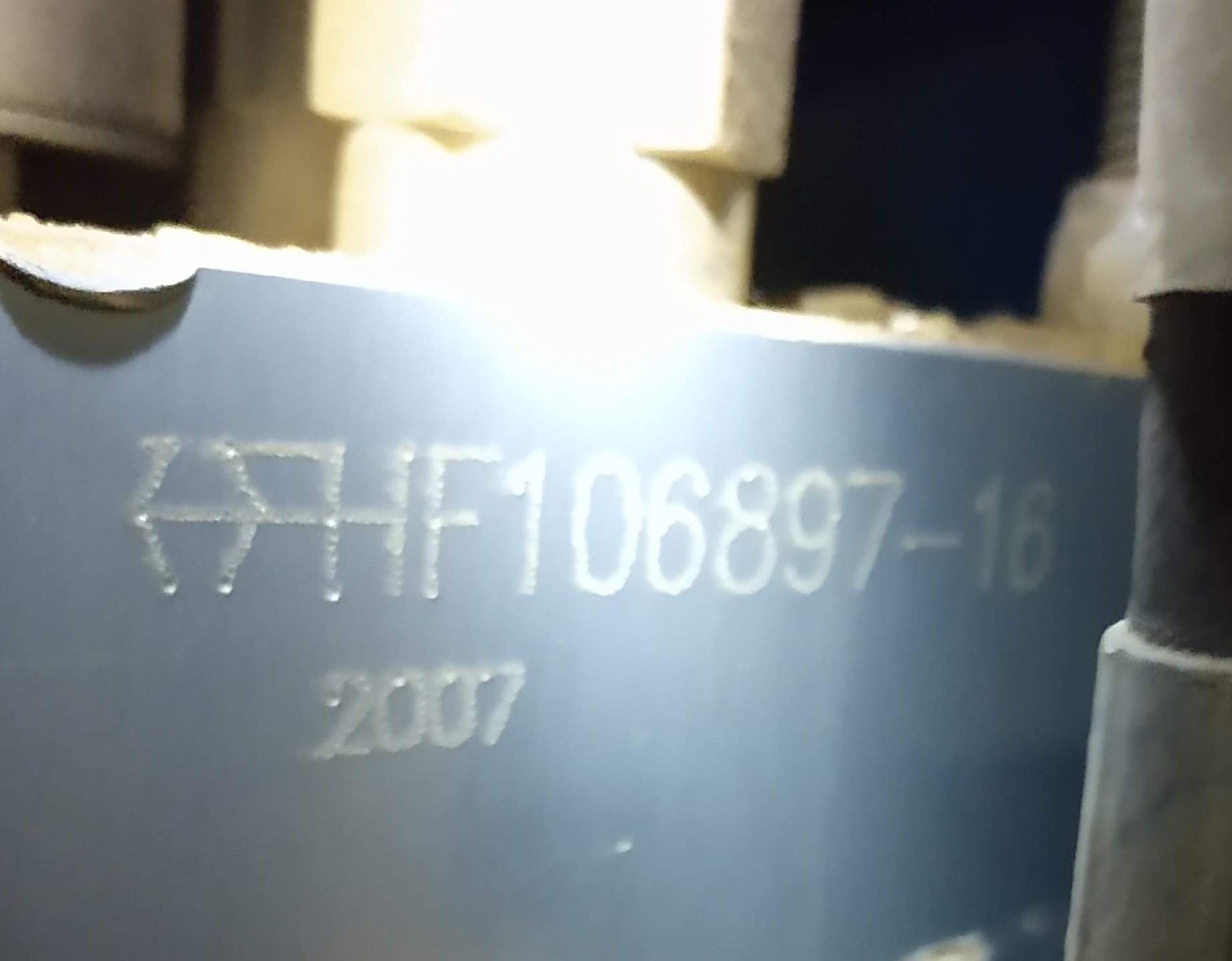
Looks like a HYDRAFORCE valve, but they can’t that part number “HF106897-16” Search not listed under obsolete, so it’s properly a custom valve.
regards / good luck with project.
Kim
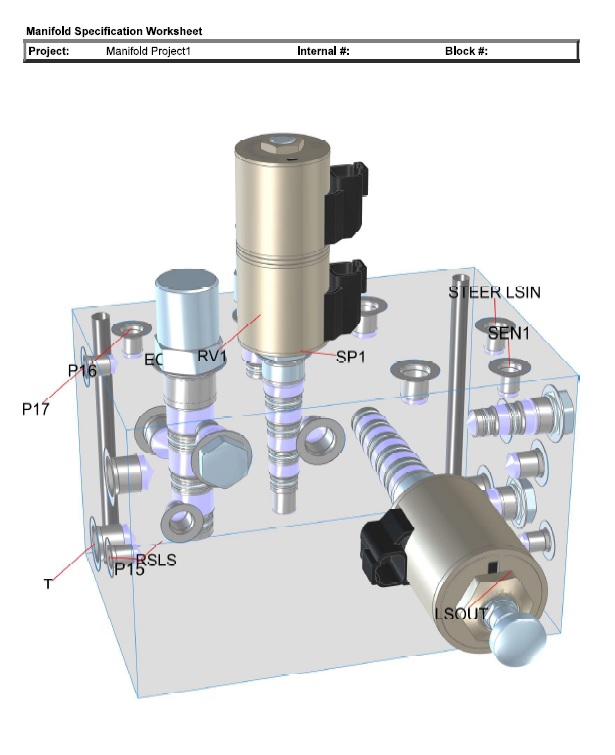
The upper schematic has the Hydraforce part numbers from the cartridges listed on it. It is a Hydraforce made valve. We bought a 6 port 2 way valve to act as the cuttoff and a ball type load sense shuttle to feed the orbit line steer pressure to the override sensor. (can’t see in photo) I’d really like to find more of these valve blocks. This setup would work on either open or closed center systems. All of our tractors are open center types.
We added the oil cooler on the return line just in case the additional heating would over temp the hydraulic oil in the steering pump reservior.
Redrawn the entire needed schematic using Hydraforce free version of design software. Unfortunately, it seems when laying out a 3D block you have to pay for the software to actually do the drill locations. This design could be used on Load Sense or non load sense systems, open center or closed center just depends on external plumbing.
Steering override sensor: Uses SEN1 if open center and you need to detect operator override from the Left Right lines. Use SEN2 if its a load sense system and steering orbit LS goes into STEER LSIN. Then a LS line to the pump would come out LSOUT. On a closed center system the power beyond port AG can be plugged.