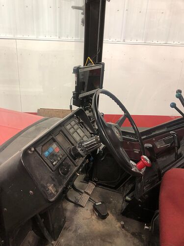
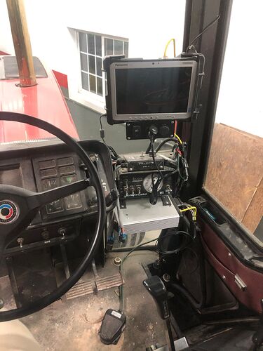
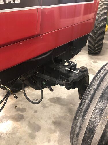
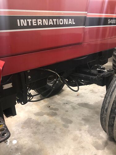
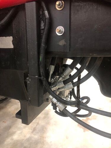
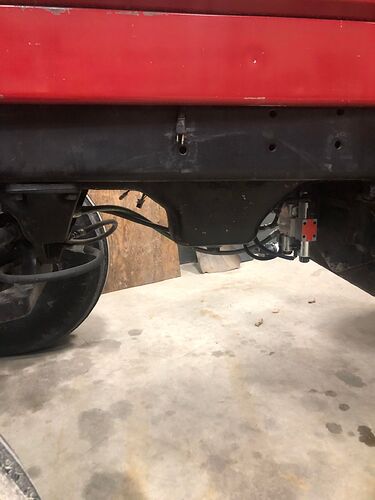
I figured it was about time to officially call the project a success and share some pics of the final product.
I have the tablet on a Ram mount off of the A-pillar. I recently upgraded to the size “C” ball and socket for more holding power. I have a little enclosure under the tablet with a 12V outlet, and USB adapter. I was originally hoping to charge via the USB, but that didn’t end up working out with the FZ-G1.
The (headlight) rocker switch is the “work switch”, and the foot switch is the “steer switch”. I’ve quickly realized that I want a different setup with the work switch and steer switch. In the future, I want to convert those to reside on the first hydraulic lever so I can easily toggle the work and steer switch when raising/lowering the implement. I’ll have to come up with a joystick for a few buttons and switches on that lever.
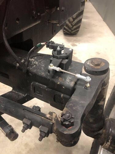
Surprisingly, the WAS mount was one of the unexpected aspects of the project that took a long time to perfect. I ended up using weld nuts on the axle to mount the spacer/riser thing, and one on the steering arm for the link to the WAS sensor. I wasn’t happy with the mount until I put an 8mm shaft through 2 608 bearings to support the arm. Relying on the sensor itself for any sort of mechanical support of the sensor arm was a no-no, and was asking for trouble. It uses a sensor from the local JD dealer.
At the heart of the system is the Baraki OC 30L valve. I originally thought that I was going to try to fit it under the hood, but I’m glad I didn’t. When I got the valve, and started playing around with the fittings and hoses, I quickly realized it was going to be too tight of a fit. I had an issue to work through with the valve, and thank goodness I had good access to it. It’s tucked in just behind the engine pan.
I’m working on a clone of this system for a 5088. A couple of things I’ll do differently this time:
- I’ll have to come up with a different WAS mount, since it has a round axle tube instead of a nice square one like this tractor.
- Like I mentioned, I want to make a hydraulic lever joystick for convenient placement of the work and steer switches, and forgo the rocker/foot switch setup I have with this tractor. I’ll probably upgrade this 5488 once I have something figured out.
Other than that, I’ll do everything about the same as with this 5488.
13 Likes
Awesome job! It’s always cool to see others installs and success, especially on tractors from the pre-GPS era!
I have a 5488 FWA that is currently getting a kit put on it. It’s getting an electric motor for this spring but will eventually get a hydraulic block. I will definitely copy your placement of the hydraulic valve. seems like it’s a good spot for it. Once i get the hydraulic valve, the motor will be put on my 5288 sometime before spring next year. I also have the ih front axle on my 5288 so I’m curious to see what you come up with for the WAS.
1 Like
Awesome! Good to hear that more 88’s are living on.
I’m just starting the install on the 5088. I settled on welding a small piece of C-channel on top of the round axle tube to create a flat mounting surface inboard of the tube pin. I’ll share some pics when I have it finished.
Do you have a part number for the Deere sensor. I have a case ih 7110 and a 7220 I want to set up. Both are 2wd and the front axles look identical to the 5488 axle in pic. Do you have pics of was components before you assembled them. I think this setup would work well on my magnums
The JD part number for the sensor is RE336709.
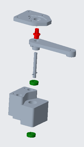
Here’s the rest of the components. The arm, key, mount, and block are 3D printed in ABS. There is a small length of 8mm shaft that runs through (2) 608 bearings.
The connecting rod is a 1/4-28 Stainless threaded rod, (2) 1/4-28 ball joint ends, and (2) 1/4-28 jam nuts.
I’m happy to share the printable geometry and you can put one together yourself. I also could print and assemble everything for you for a fair price…let’s say $100 USD with everything but the sensor. Let me know what you think.
I have a 3D printer if you have the stl files I could try printing it
Here’s a slightly updated version than shown. There are (4) 3D printed parts: bearing block, spacer, sensor mount, and link (with the sensor key). I’d print the link on its side so the key doesn’t shear off in the sensor.
88 series WAS parts.zip (477.2 KB)
I forgot to mention that my means of securing the 8mm shaft to the link was via a 5/32 roll pin. I had a hard time drilling the hole, so I changed it to a D shaft. I took my 8mm shaft, ground a flat spot on it with a hand grinder, heated it a bit, and squished it into the 3D printed part. That’s a lot easier than the roll pin.
Thanks for sending stl file
