Hello everybody!
I’m looking at Trimble WAS and I can’t see any mechanical connections with axle. So in my opinion it runs with some IMU and my idea is to use IMU brick as a angle sensor. We have BNO/CMPS and GNSS heading and mayby in some way use another IMU mounted on axle to have wheel direction? This topic is for tech guys, maybe someone just did this…
I recently been working on this.
Hope that next week I will be able to test it and come back with some good results.
Some testing that I done manully was promising.
Small errors of around 0.50°.
“My opinion” is that the Trimble sensor is a hall effect sensor like most WAS sensors used by forum members. Googling some Trimble sensors looks like the magnet is differently placed, outside of the sensor box?
How does this IMU read out if you turn the steering wheel and keep on driving? How do you calibrate the IMU to read zero degrees?
What would be the advantage of an IMU based sensor over a hall sensor? Certainly not price or simple setup.
Always interesting to see new ideas but I would always like to see more background and explanations.
For me, the installation is much simpler. There is no mechanical boundary to which max angle you can read. Not too much brainstorming.
The general idea is to use the tractor heading and the wheel heading and to use the difference in these two angles. It can be zeroed as the old WAS.
As we know the heading is stable when fused with GPS, both headings will be fused and then the steering angle will be calculated.
1 Like
Hello,
Finally, I had time to create a POC(Proof of concept software) for the IMU as a WAS.
So I have something working currently and will gladly share the video with you guys. So the next steps from my side are to refine the code and do some real-life testing. I hope that it will be finished next week and ready for testing. When I finish the first refinement of the code I would like to ask you guys to do some testing as well.
The setup is pretty simple.
You just need one additional BNO and some kind of I2C extender. I am using @BGunics external IMU board. Huge thanks to his board for making this a lot easier. GitHub - gunicsba/AOG_ExternalIMU: In order to put BNO remotely
For the wiring, you just need to connect the WAS_IMU D1-pin to the VIN pin. And connect the external IMU board to the existing pins on the board.


Here is the video as well.
As I said this is currently in the POC faze so it is not ready for real-life testing. I will have a working version by the end of the next week. So please be patient.
I will upload the files on github and post a link here when the first version is ready for testing.
Best regards.
4 Likes
Great idea!
It’s so nice too see that the board works for others too ![]() We had some trouble where sometimes BNO wasn’t recognized, but utilizing longer / different cables it worked.
We had some trouble where sometimes BNO wasn’t recognized, but utilizing longer / different cables it worked.
As for your project: I think the first real-life challenge will be to figure out the 0 position. As it likely will drift and be different from the main IMU. (But chances are it might only need slight offset.)
For that @PotatoFarmer did some code where basically he looked at the XTE changes on AB line and when it wasn’t changing then the wheel must have been centered, so the offset could be adjusted to that. I think that should work here too.
Ideally the steering angle should be the angle difference between the WAS IMU and main IMU.
Most tractors do +/- 30 degrees on the wheel. So we just need to think about going above 360 or under 0 degrees.
The ones that come out these days use Imu instead of was. Installation is very easy and good. I hope you succeed.
I hope you get out of the difficult IMU installation.
Need to think about how it will react on a muddy or rutted field where the tractor is going straight but the wheels are turned. Also, side hill would be another case to be handled. Might need to bring roll into the algorithm.
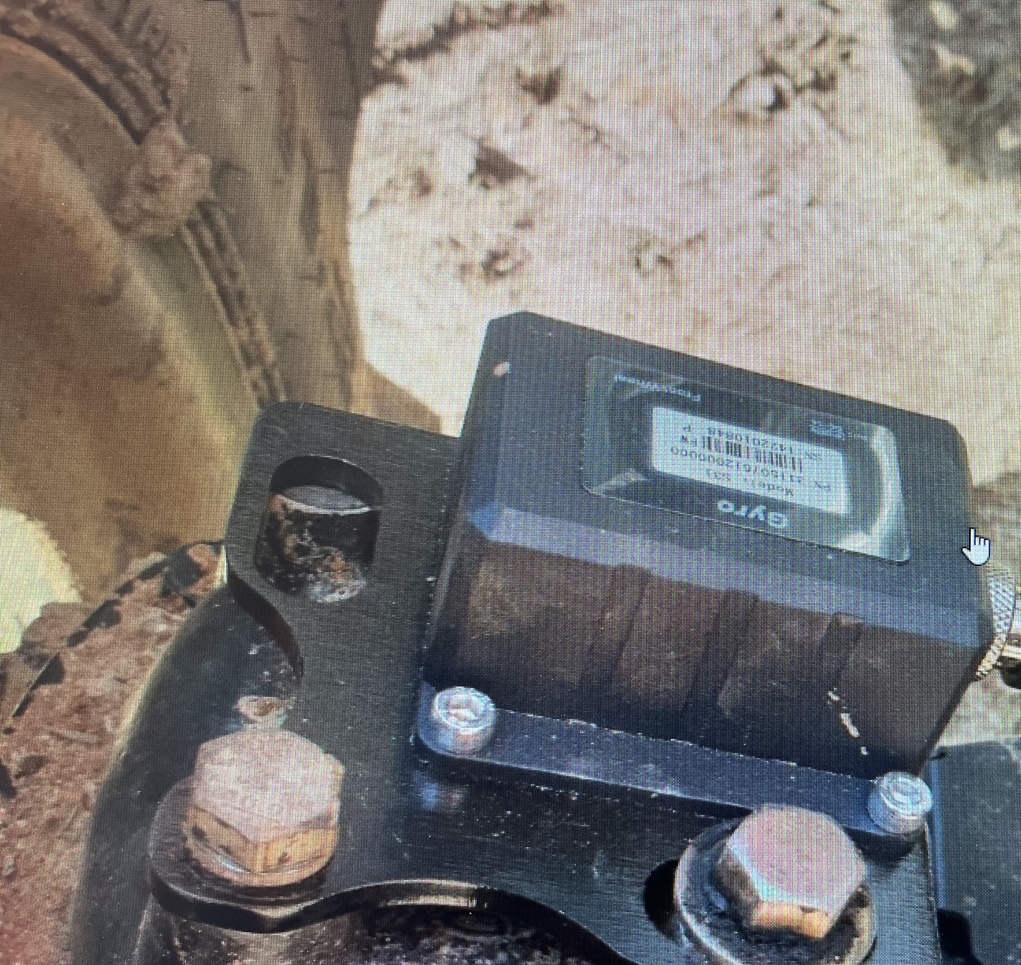
Case uses the Timble gyro as a wheel angle sensor. It works alright. But it does require the tractor to be moving to figure out the angle. So at very slow speeds after starting out it wiggles all over the place. Very annoying on a sprayer. I’ve not analyzed the CAN messages coming from and going to the gyro unit, but I would think it would have to have GPS input to calculate the actual wheel angle, or at least compare the main IMU yaw with the gyro yaw. So I don’t think it’s as simple as just replacing the WAS with a gyro without code in AOG.
In my mind a physical WAS sensor with linkage, although prone to breaking, dirt, etc, is the simpler and more reliable solution for AOG. And in fact it’s the solution that most commercial systems choose as well.
1 Like
The main idea is to have an option. It can be integrated in the system so that users can choose what they want.
I agree with the current WAS as a really good solution if not the perfect solution.
We will see and there are maybe some users that would like to try this solution.
1 Like
Yes I agree rhat the rool should be accounted for.
How do you envision this working with AOG? Does not it need extra computations and modifications to AOG to work?
Just change the code and everything else stays the same.
I’m not familiar with this board, but what interface will be used in the future? Can bus or rs232?
1D Kalman filter might need to integrate them and eliminate gyro drift otherwise angle error would arise.
Going forward it is likely the new AIO boards will feature an RS232 interface. With RS232 and the BNO running in RVC mode it should be rather easy to add a remote BNO with only a RS232 adapter on the BNO.