3 Likes
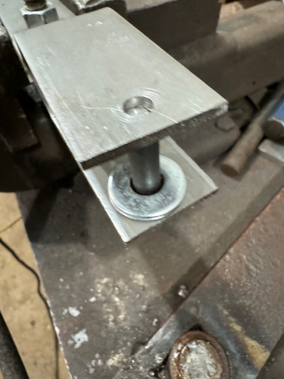
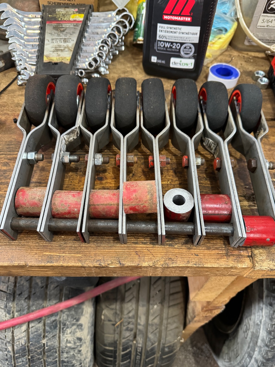
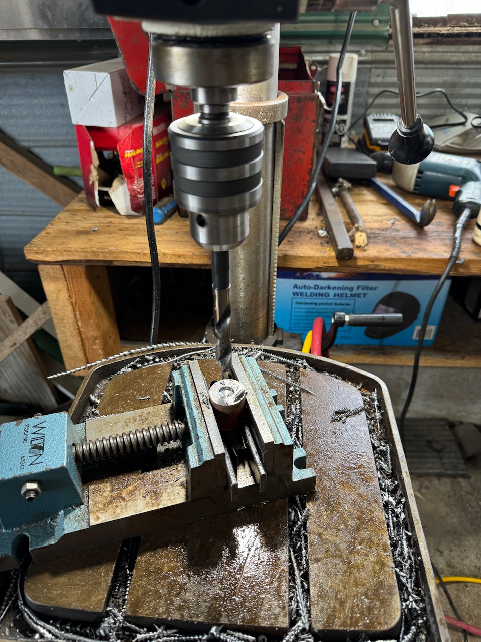
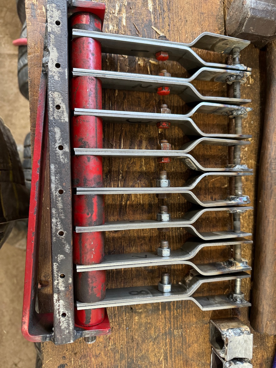
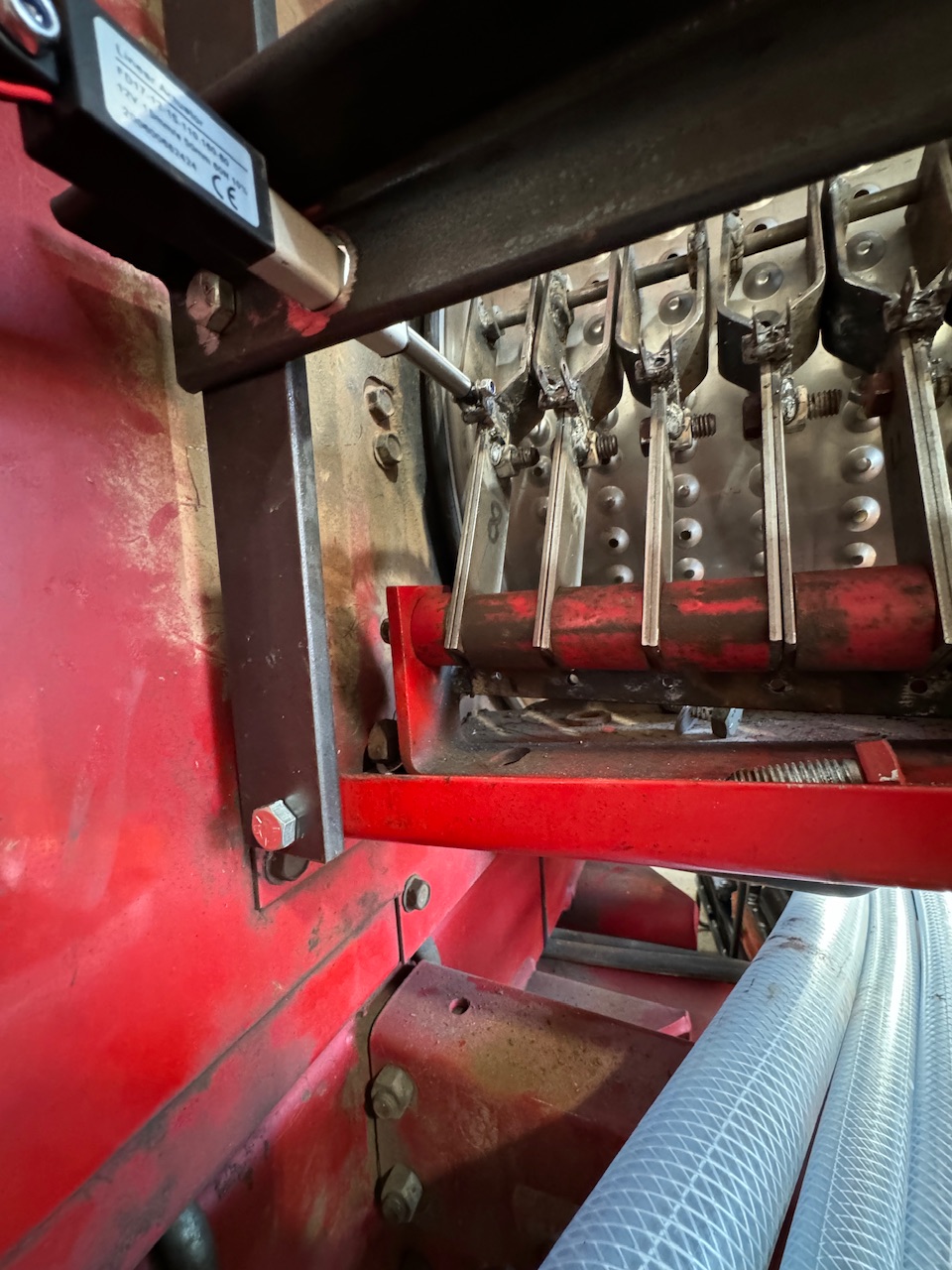
Bit by bit we’re getting there! Instead of using a bolt and a nut for the axle and trimming the head a few thousandths of an inch at a time to get the right spacing, I switched to using the same size in a rod and drilling a hole In one side of the frame and welding the rod on through the hole. Much less time consuming!
3 Likes
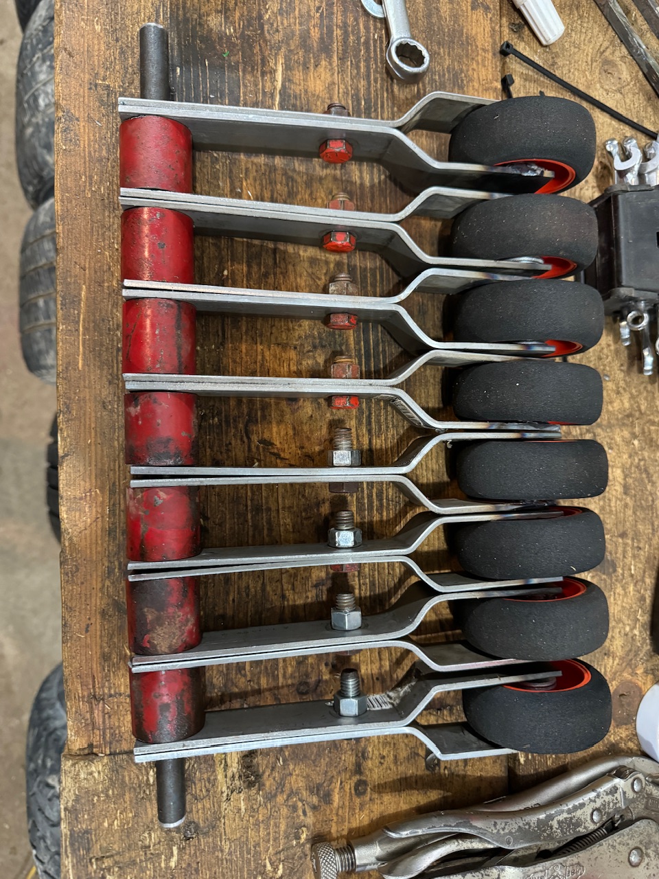
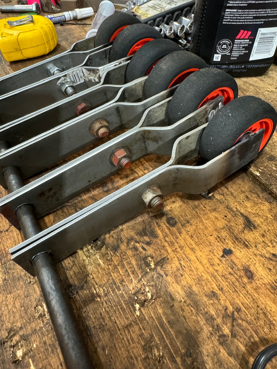
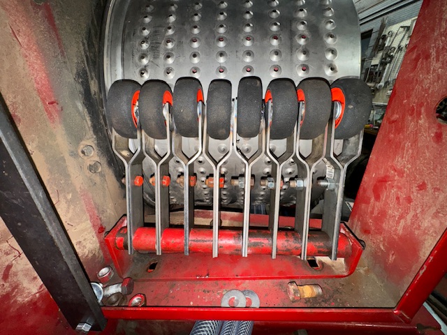
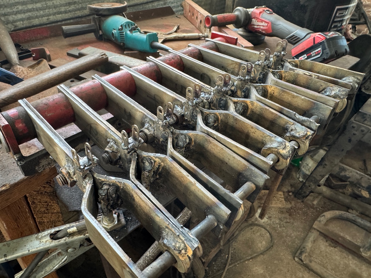
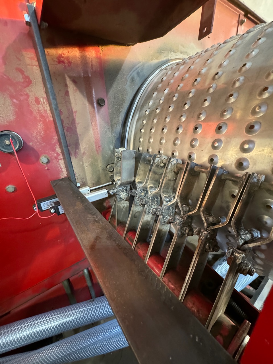
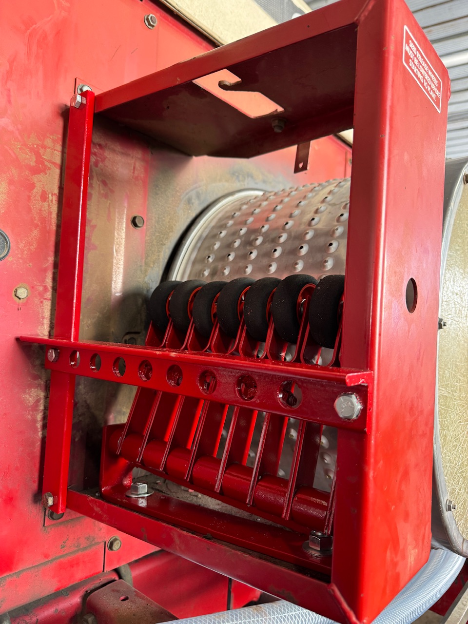
Test fit looks promising!! Some fine tuning to do to eliminate the two that are scraping against each other but they all move freely in and out. That part had me the most concerned, as these are hand bent brackets ![]() Credit for most of those goes to my Dad. I made one pair and he made the rest!
Credit for most of those goes to my Dad. I made one pair and he made the rest!
2 Likes
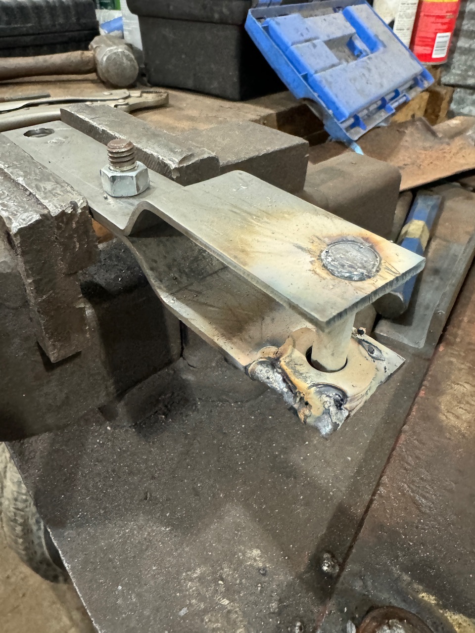
Finished the row control arms today!
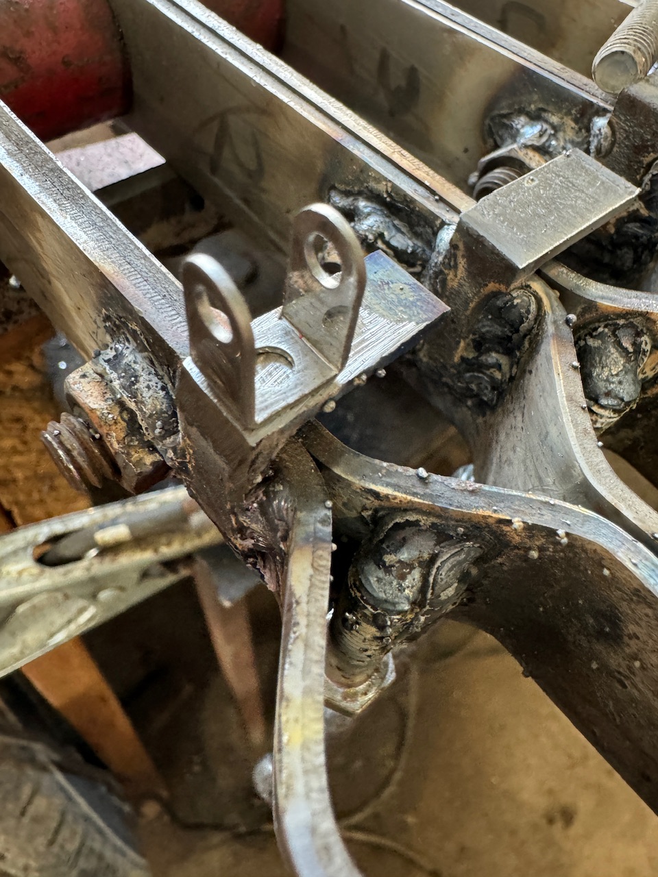
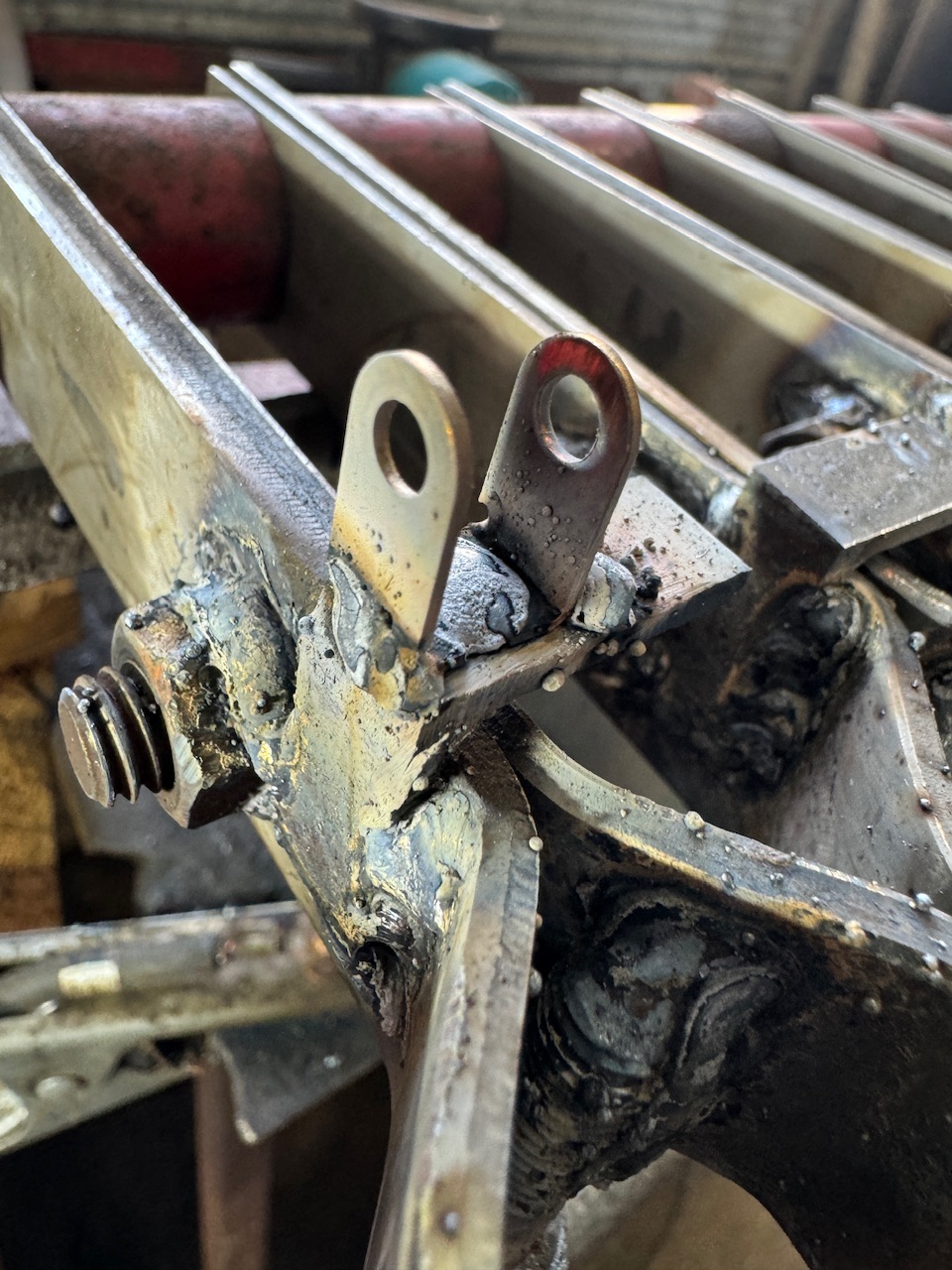
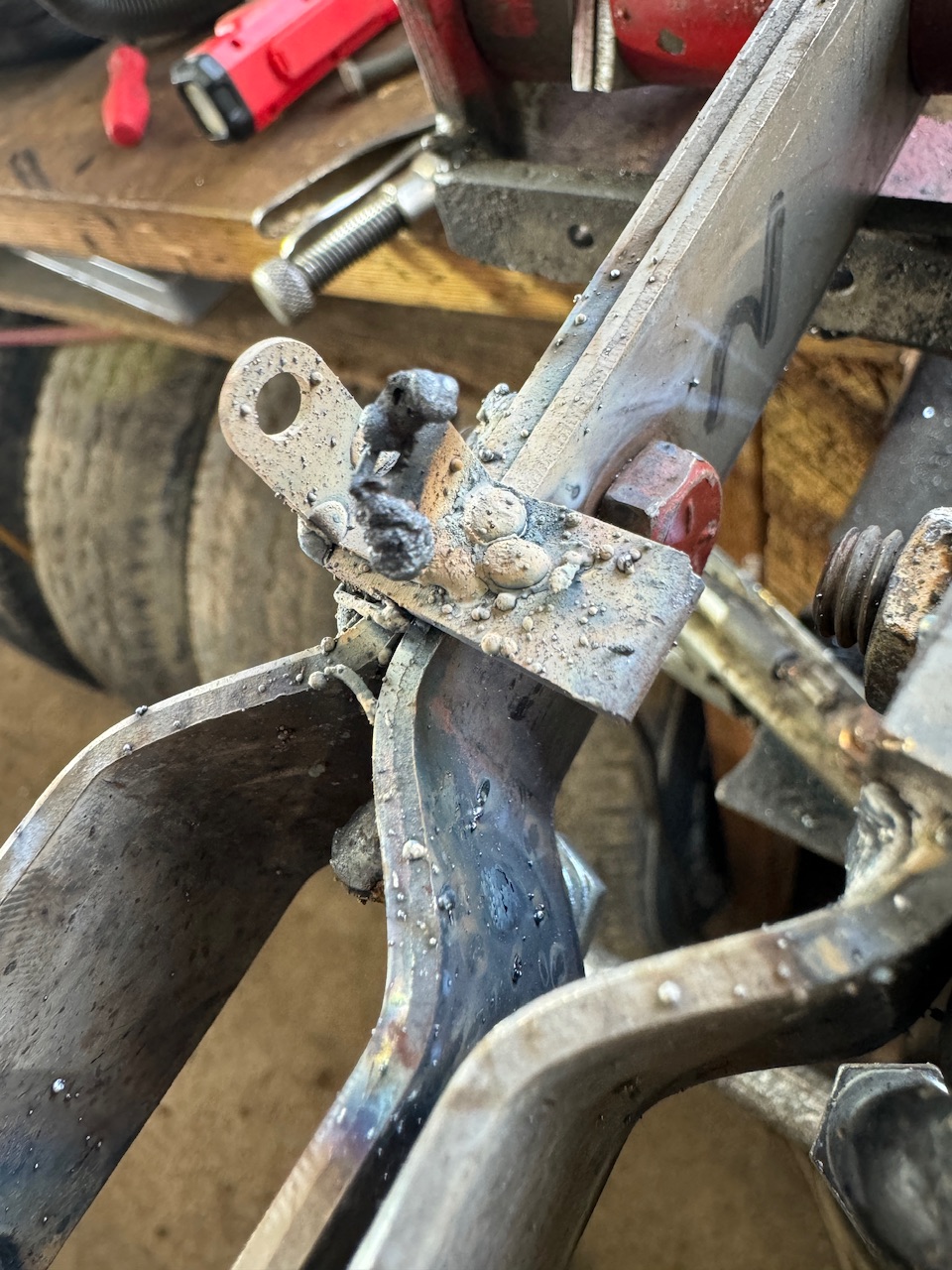
Welding these actuator brackets should not be done while struggling with depression and low self esteem ![]()
![]()
![]()
Got ‘em all done eventually lol
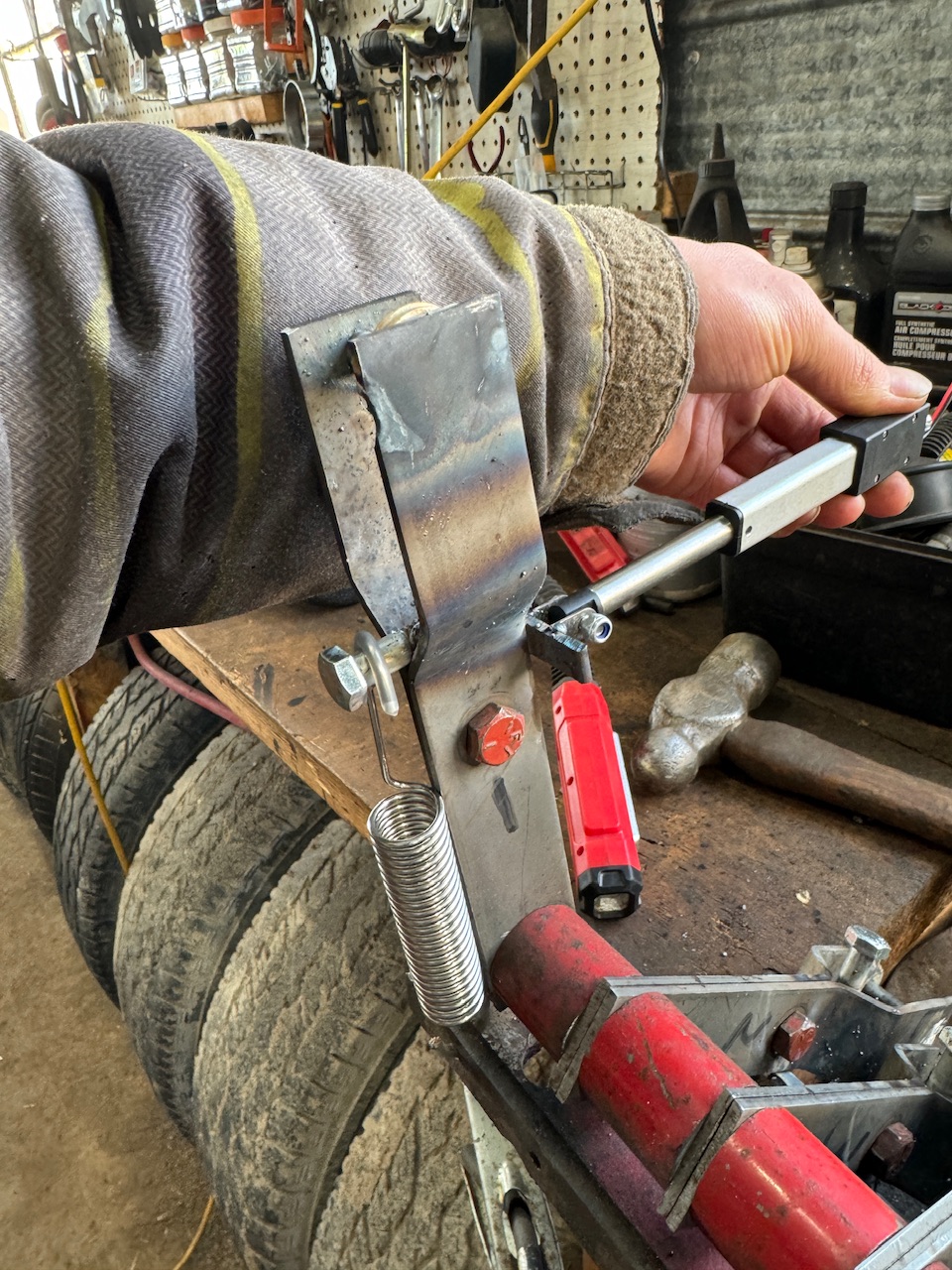

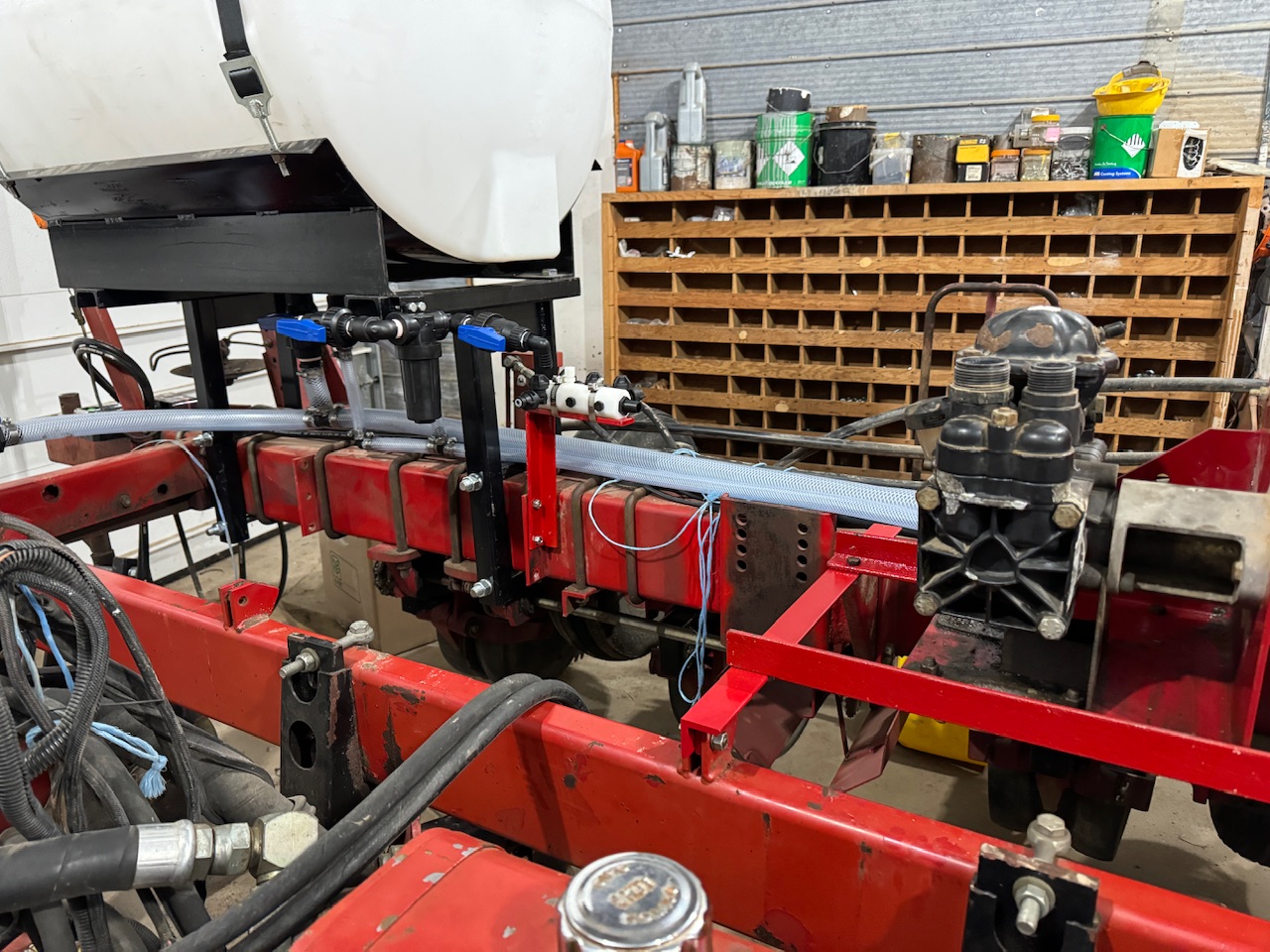
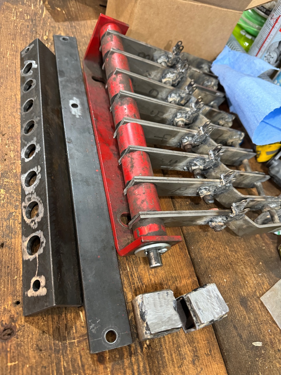
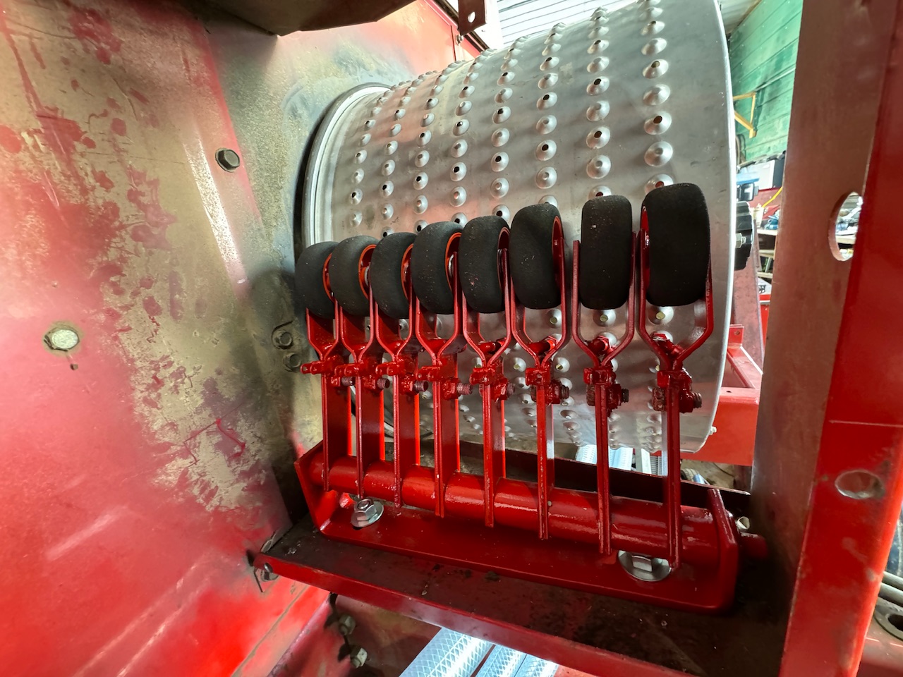
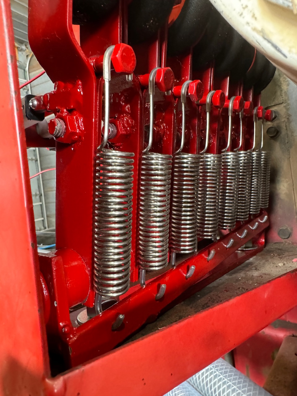
Here is the spring tensioning system
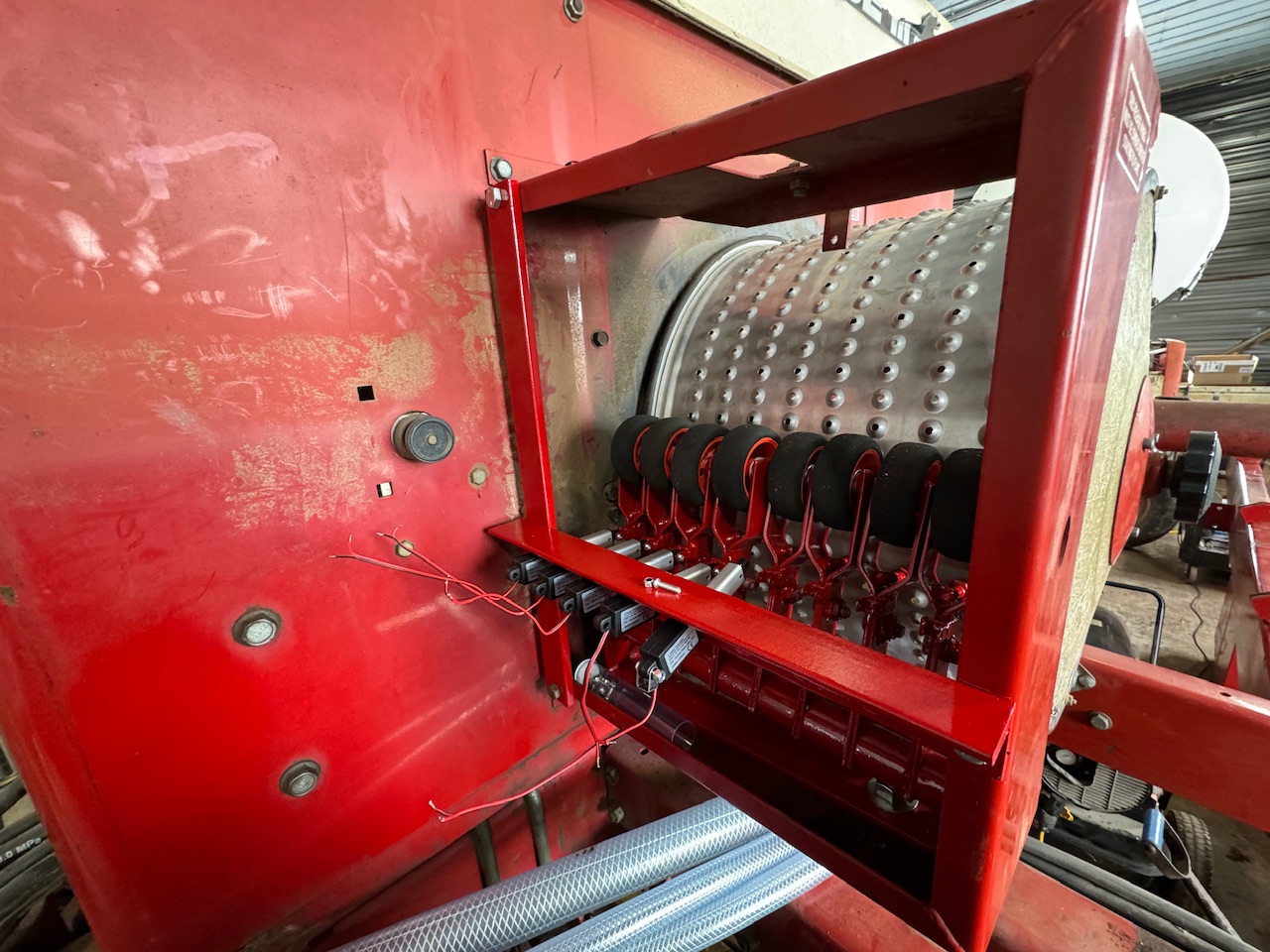
Actuator mounting bar in progress…
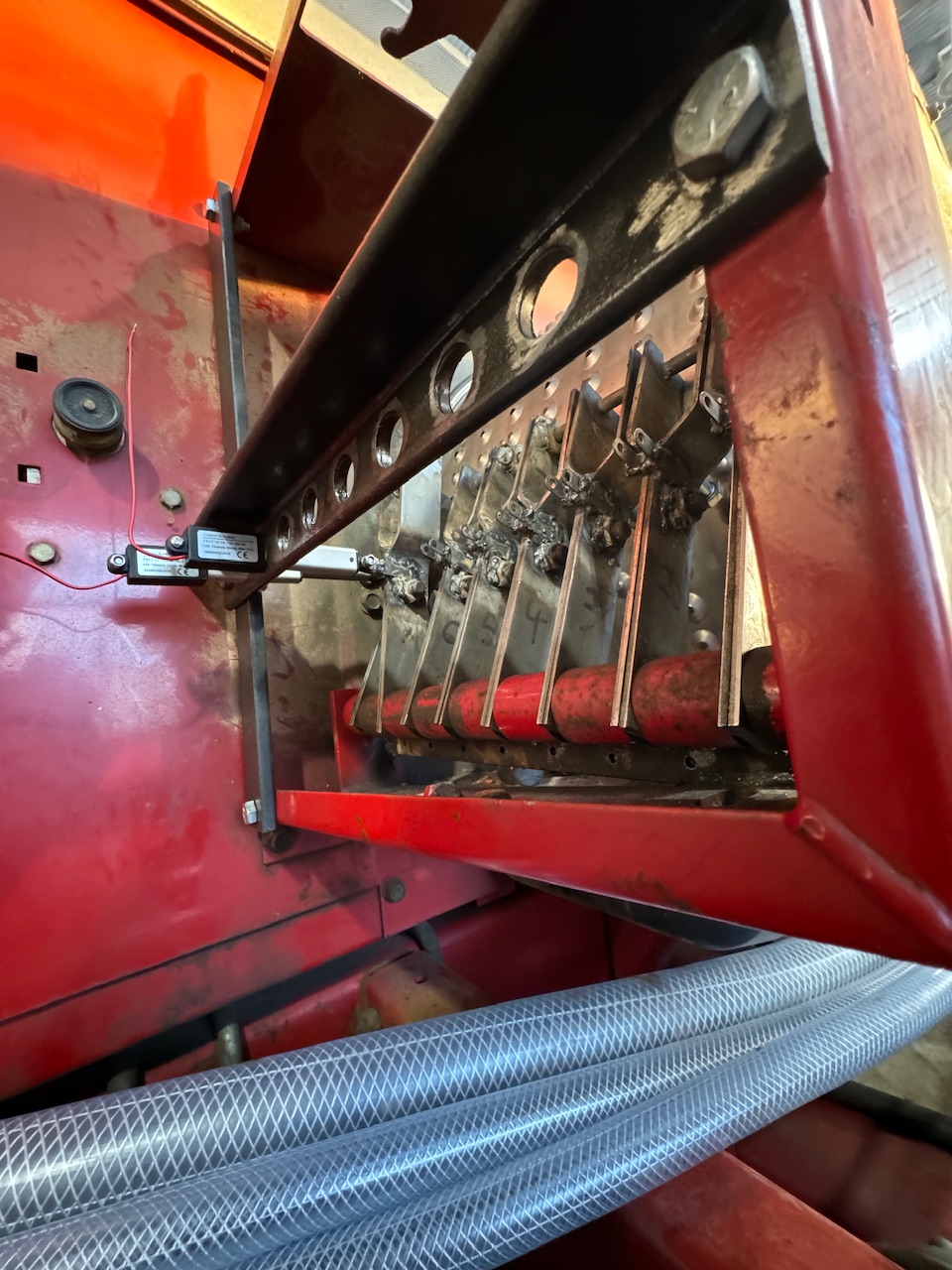
…And completed. Actuators line up nicely.And this stuff is ready for paint!
8 Likes
Hey @SK21 , a few questions about wiring up the RC11 board here.
Is it safe to power it through the amp seal, or could I use the button style connector, or should I solder a power and ground at their respective solder points on the board?
I assume the flow meter signal goes to a flow pin?
How do I know which channel of the MDD10A is which rate for a double rate setup?
Which sensor pin is sensing for which product?
And one more question, is it possible to send a speed/GPS input from a nonAOG source?
The amp seal connector can handle 8 amps with tin connectors or 17 amps with gold connectors. It depends on how many amps you are using.
The flow meter signal for each flow meter goes to a flow pin. On the module setup page in the rate app the RC11 board can be selected. The defaults settings for this board can then be sent to the module. This will setup the two flow pins. On the module/pins page the flow pins and the pwm pins are shown. Pin 28 for the first flow sensor and pin 29 for the second. Pin 36 for the first rate motor and pin 15 for the second.
The rate app requires AOG speed input. An external speed source can’t be used. The rate app can be set to a single speed and not require AOG speed input. For example you could set a constant speed of 5 mph. It would control the rate for 5 mph and the tractor would have to drive at that speed.
2 Likes
Awesome! That’ll get me going!
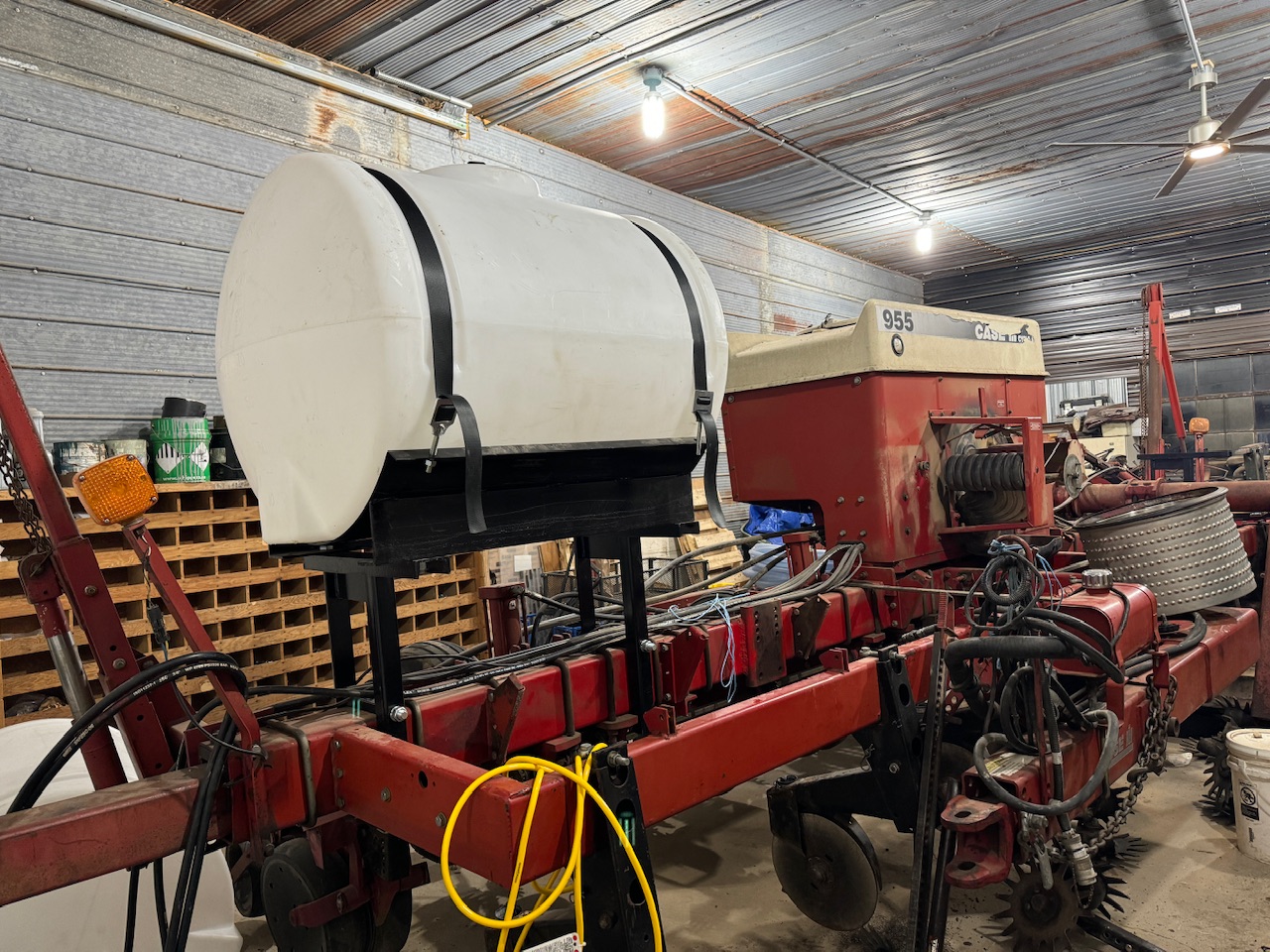
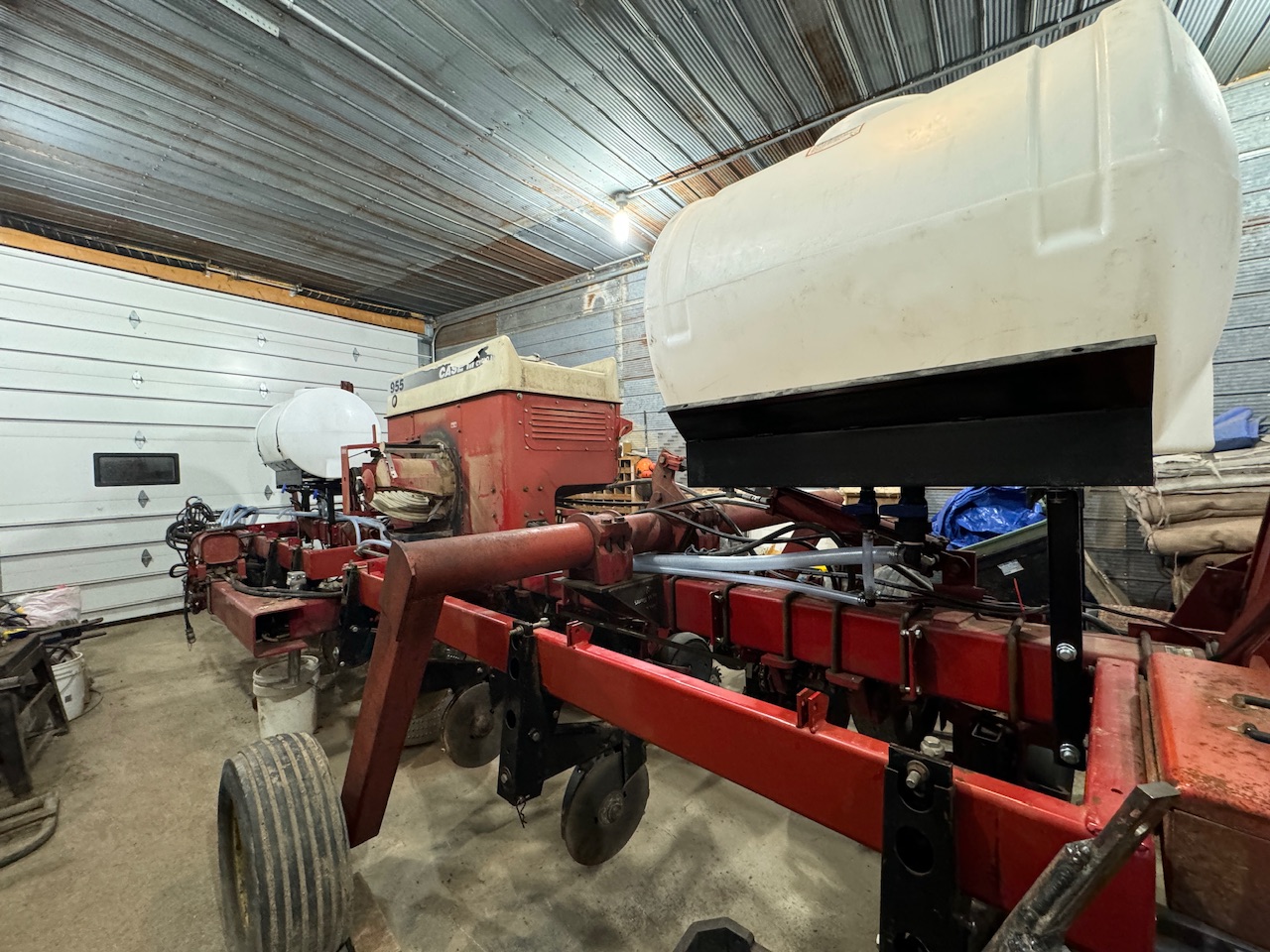
Finally had time to work at this again today. Here’s some catch up pics of what I got done in the last few weeks spare moments.
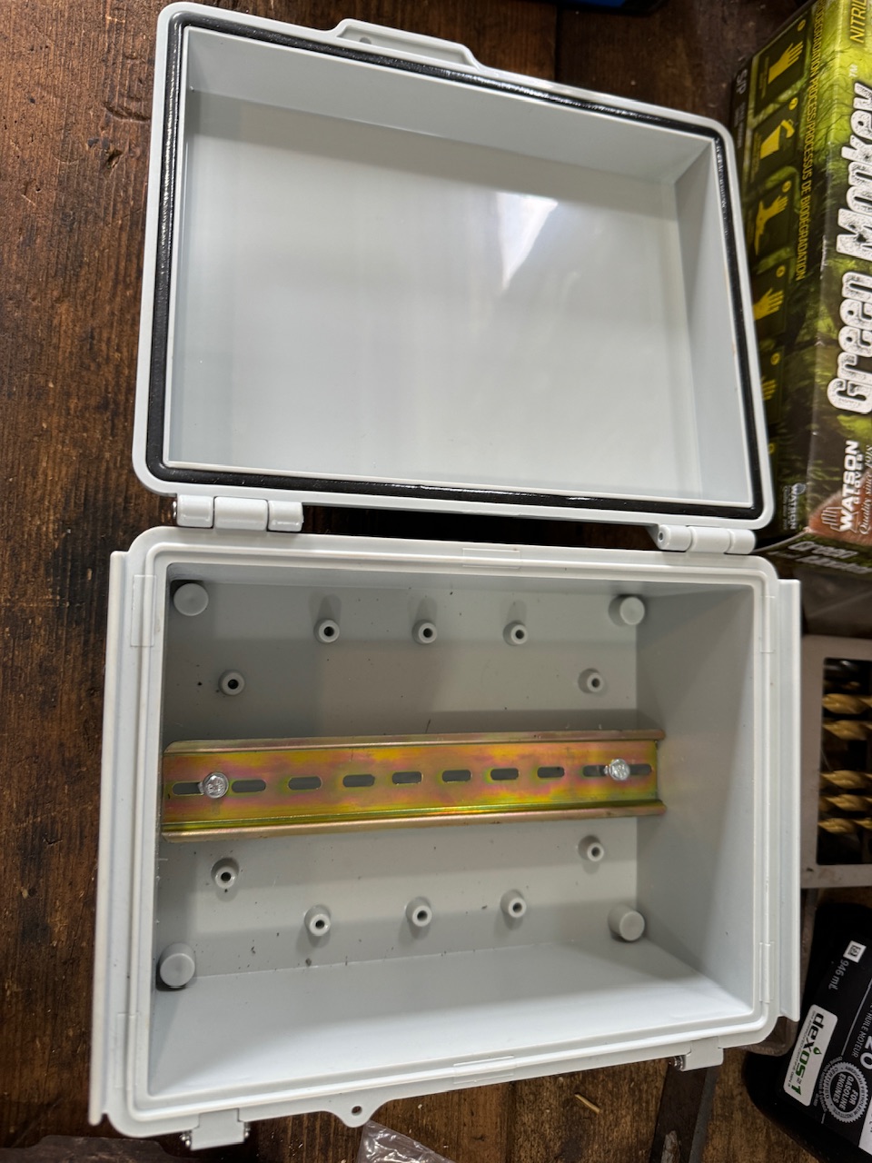
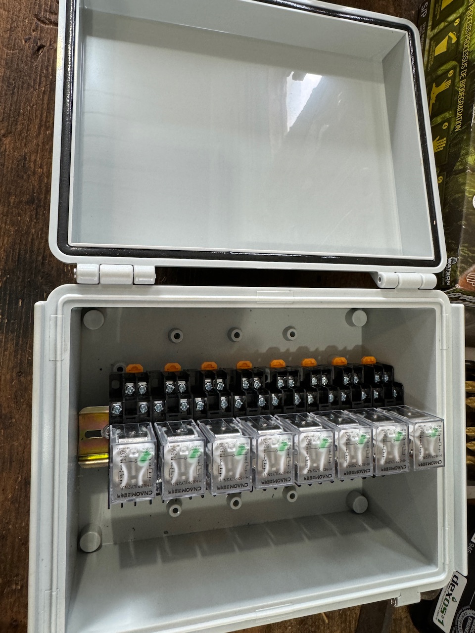
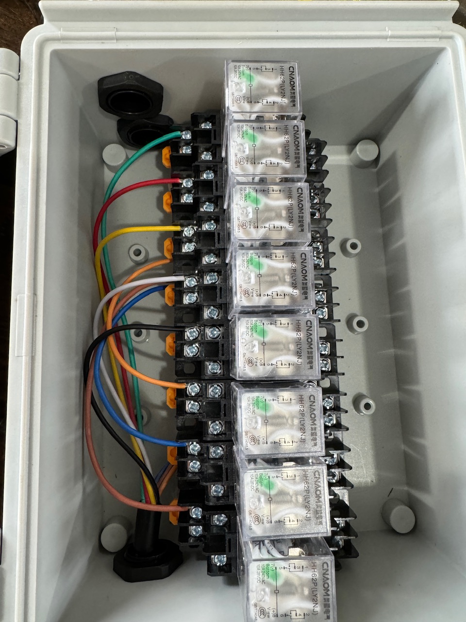
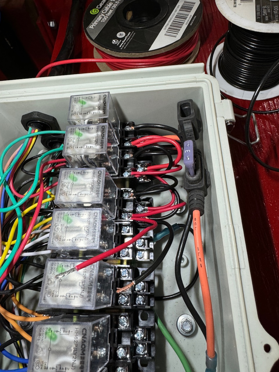
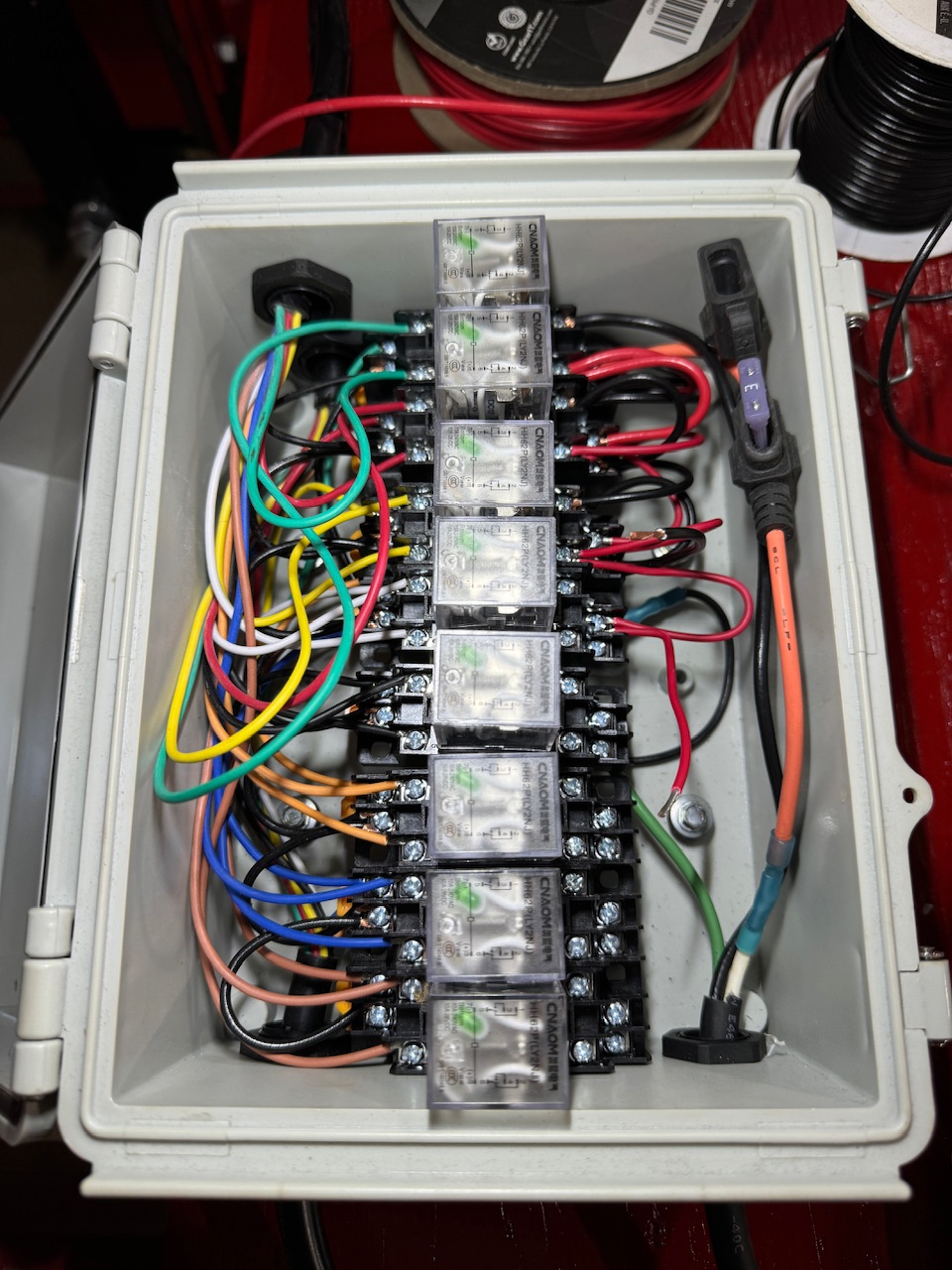
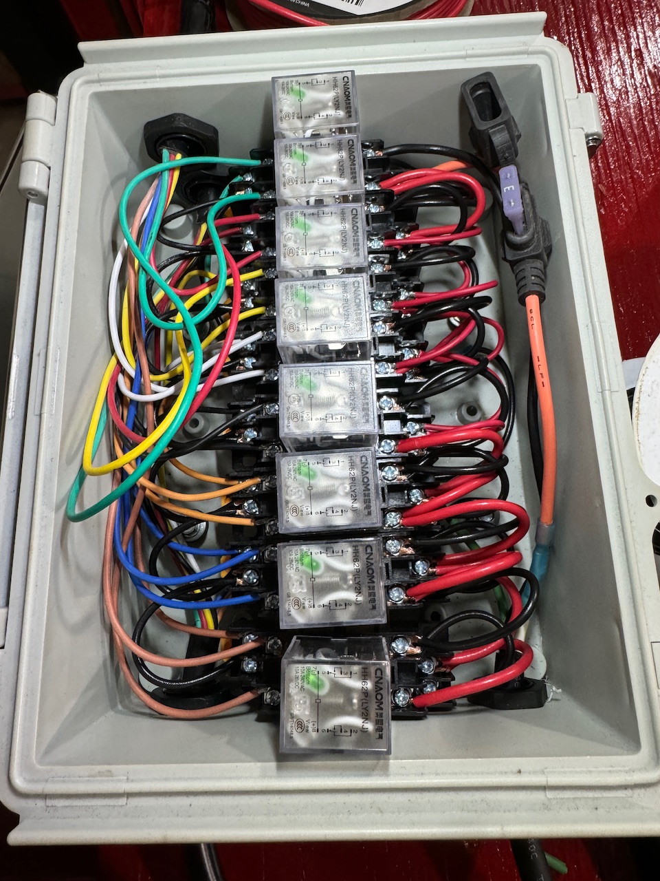
Got the signal side of the relays all set up and working. I had first been thinking I’d use 2 SPDT relays per row, but I checked around a little further and found some DPDT relays that I liked. And a second box to put them in, as the RC box wasn’t big enough to add them in there…
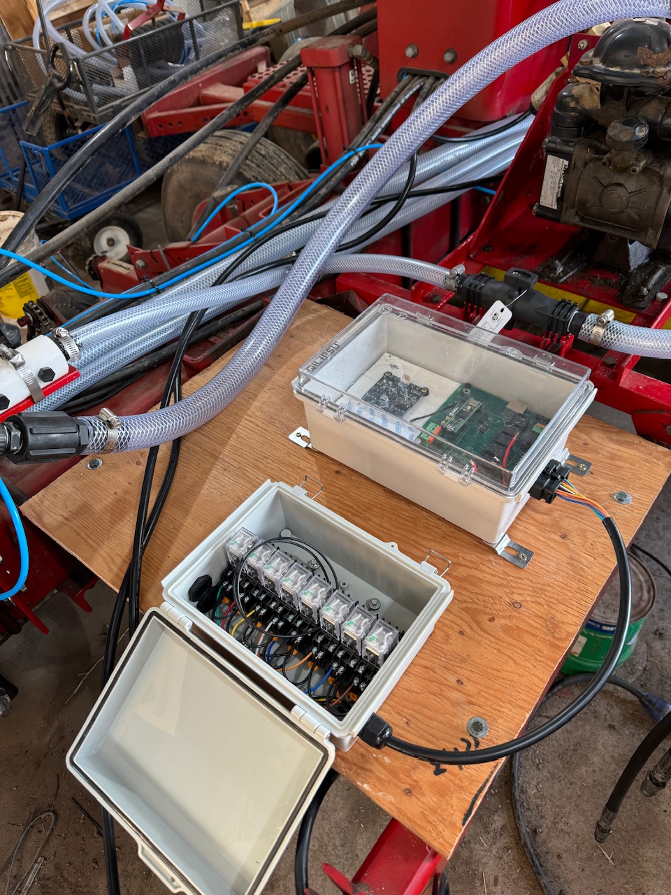
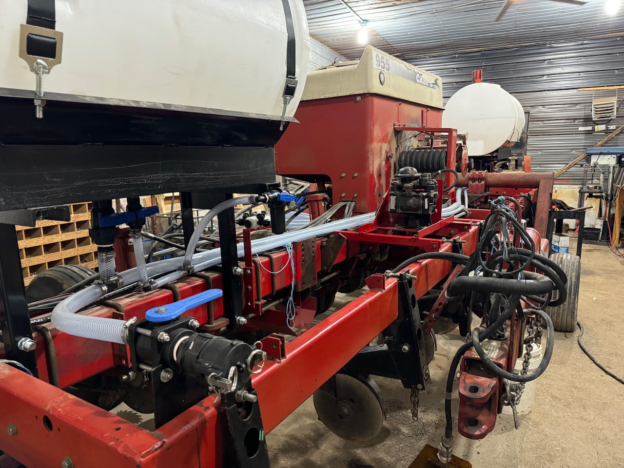
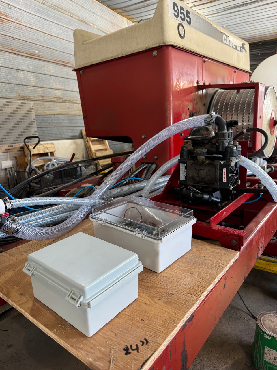
I also got the freshly painted pieces back this past week, so those got installed.
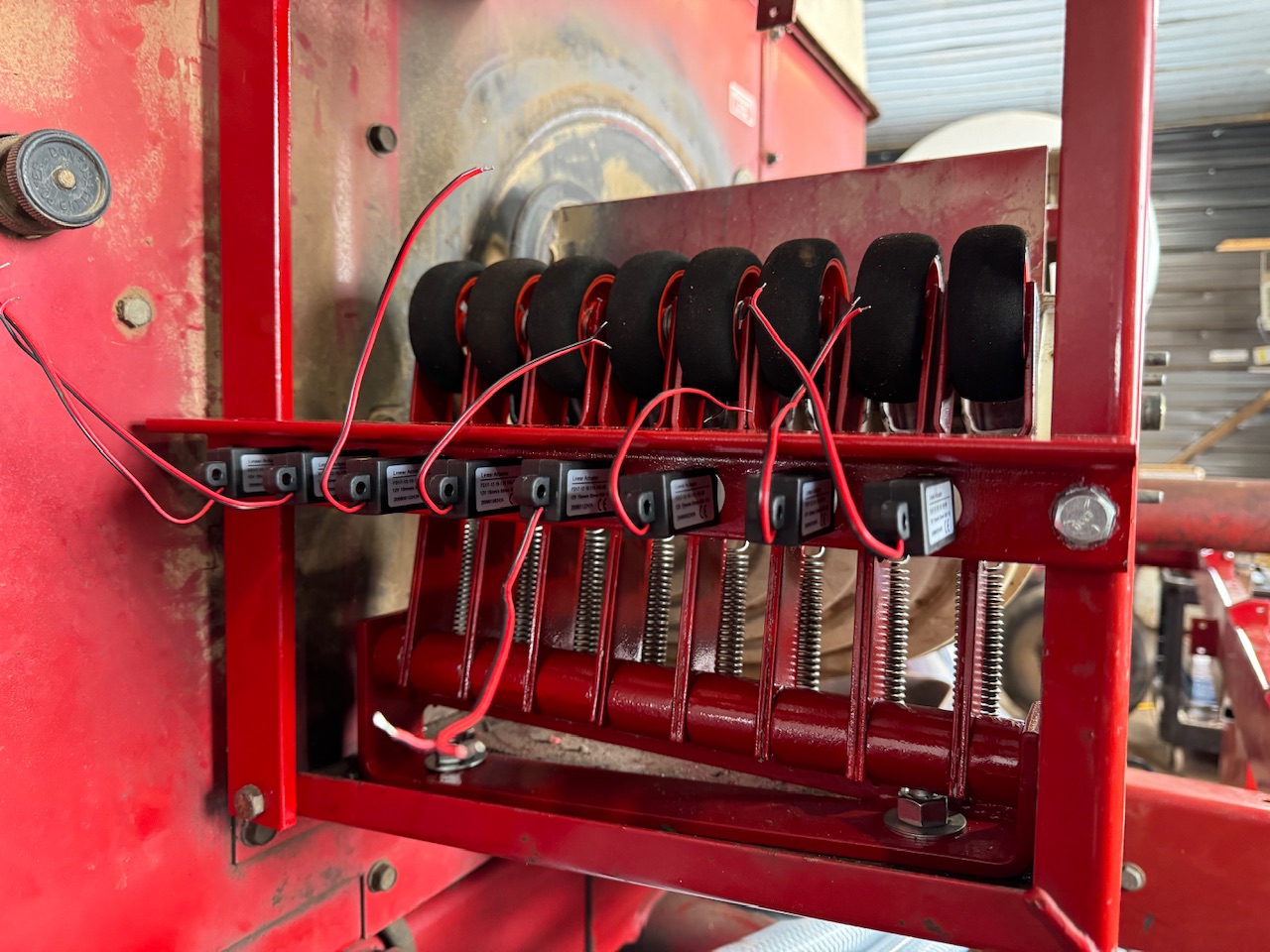
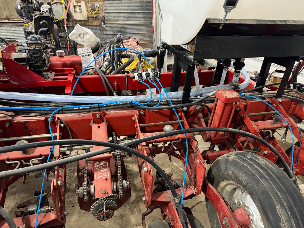
Ran the wires to the actuators. I found some 8 wire cable on Amazon, so the sections are nicely colour coded ![]()
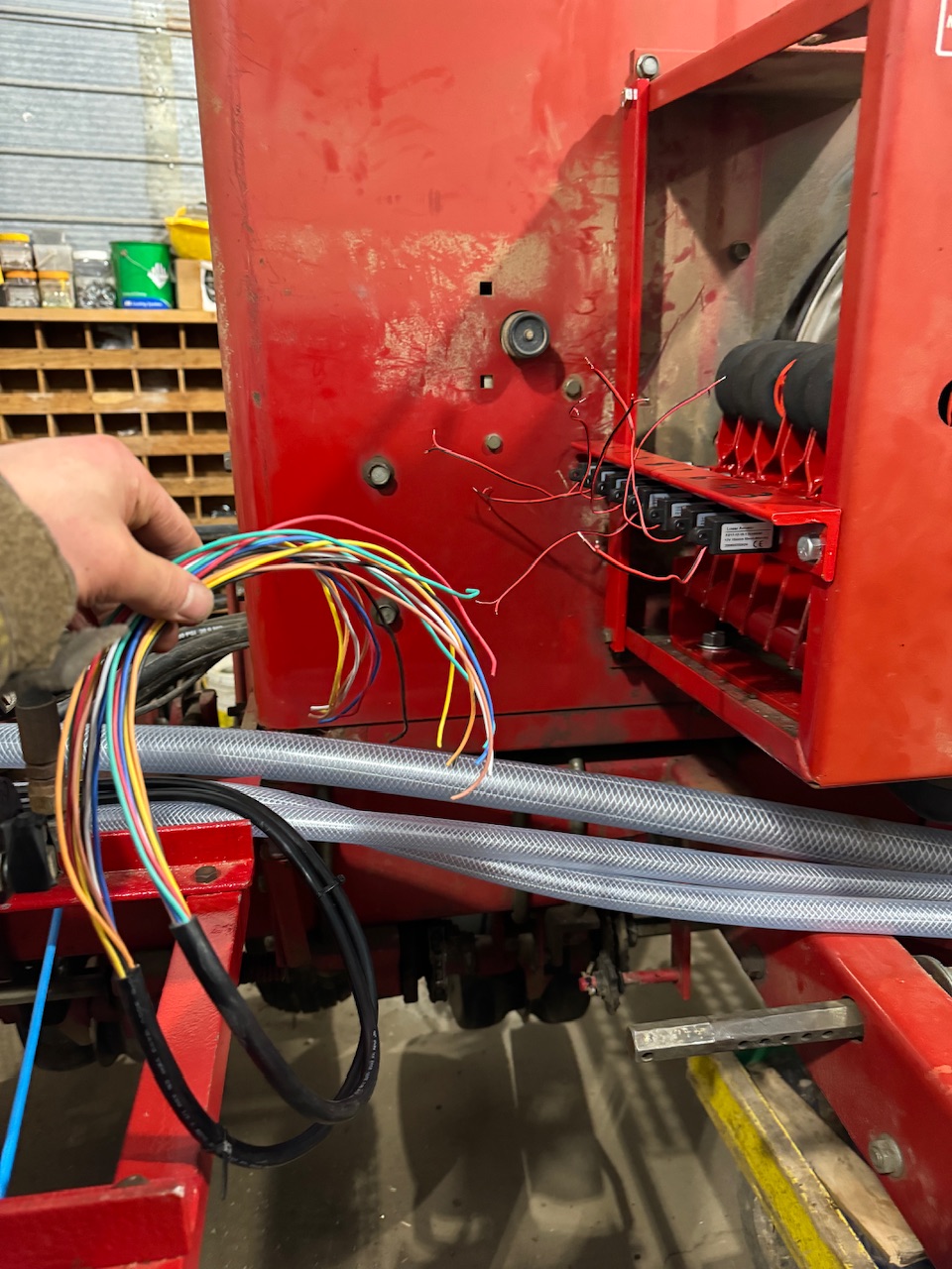
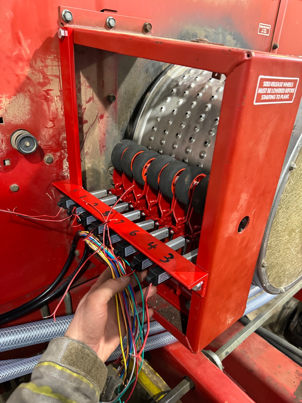
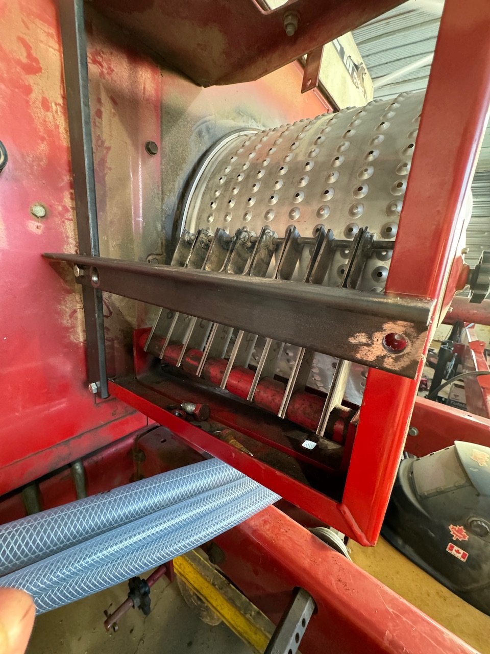
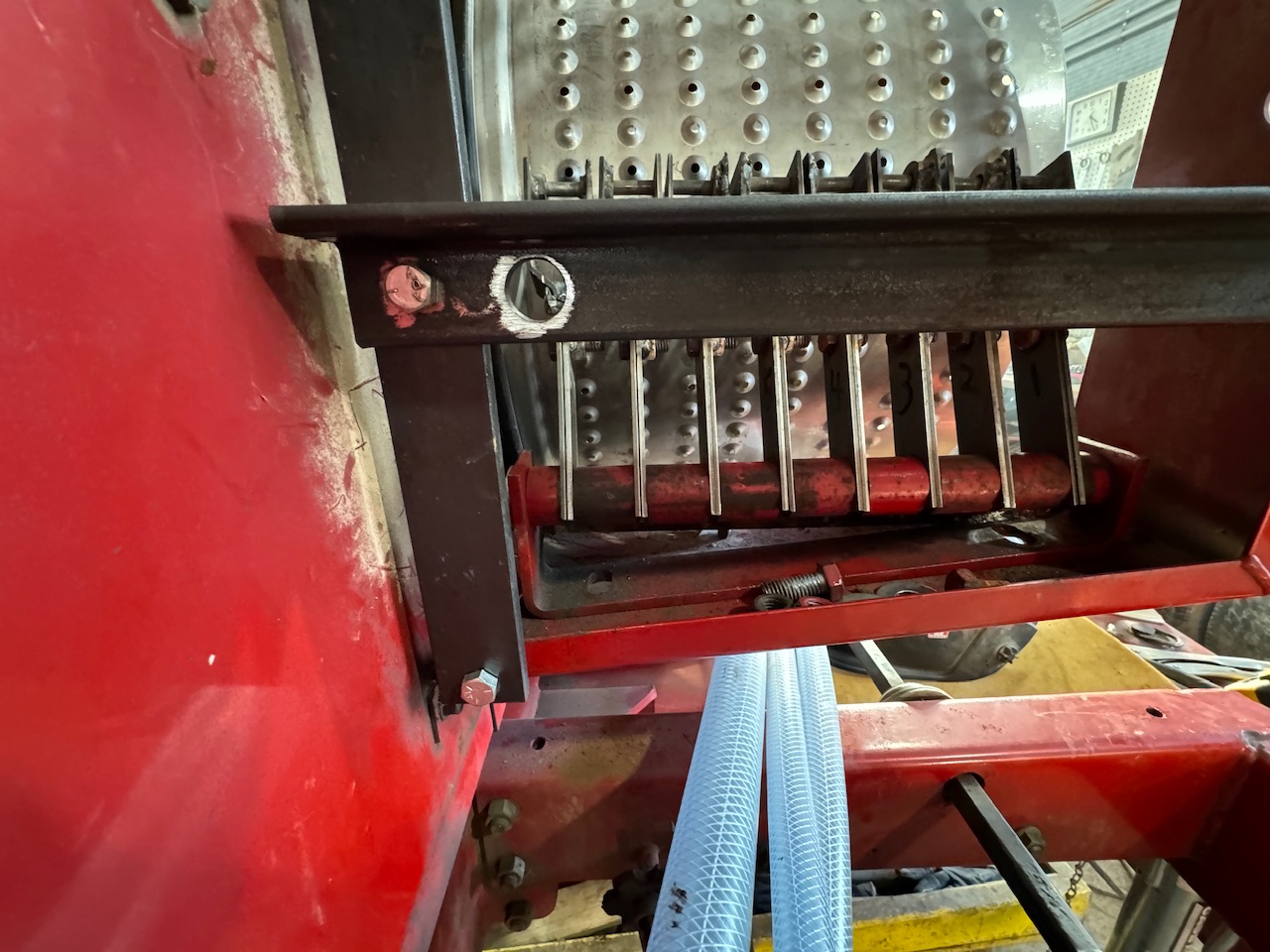
Man, whoever installed this planter’s seed hoses was clueless!!! lol I guess I’ll just have to adapt for the moment!
6 Likes
nice work!!!
Very impressive work ![]()
![]()
![]()
Thanks! I’m having a blast!
1 Like
Looks great! I like the looks of those little actuators. Would love to hear an update after a little field time with them.
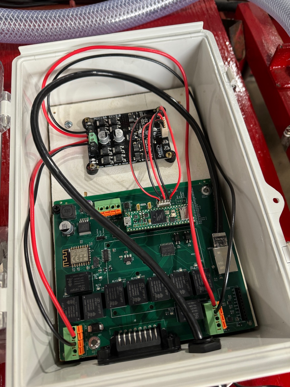
One more thing that’s a little unclear is how to wire the PWM solenoid. I’m using a Cyton MDD10A motor driver. Should I connect the solenoid’s 2 wires to M1A and M1B on the Cytron, one to M1B and the other to ground, or one to M1A and the other to ground? If I wire it to M1A and M1B as I first described, does it matter which wire connects to A or B?
1 Like
Both solenoid wires should go to M1A and M1B. Movement will be reversed if the wires are reversed. Neither M1A or M1B should go to ground. This could cause a dead short.
1 Like
Awesome! Thanks for the clarification!
Finished the wiring today and ran a test…
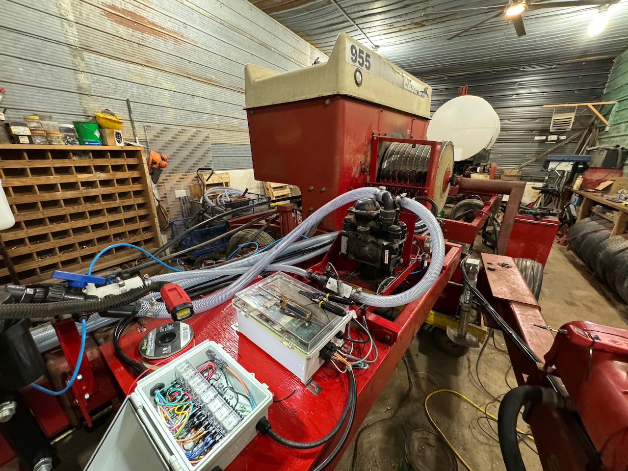
…all 8 actuators can be pulling the spring tension load and not pop a 3amp fuse! ![]() Here’s the testing videos. The first time the one section seemed to be a little bit behind. Seems to have fixed itself in the other videos then. https://photos.app.goo.gl/1WgDbNDzuvPRsjBQ8
Here’s the testing videos. The first time the one section seemed to be a little bit behind. Seems to have fixed itself in the other videos then. https://photos.app.goo.gl/1WgDbNDzuvPRsjBQ8
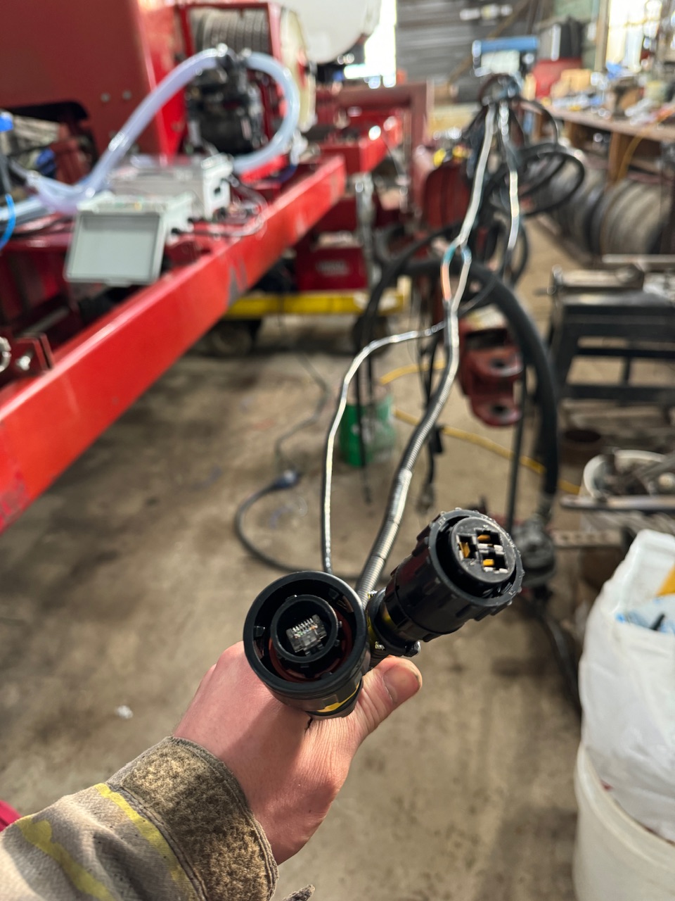
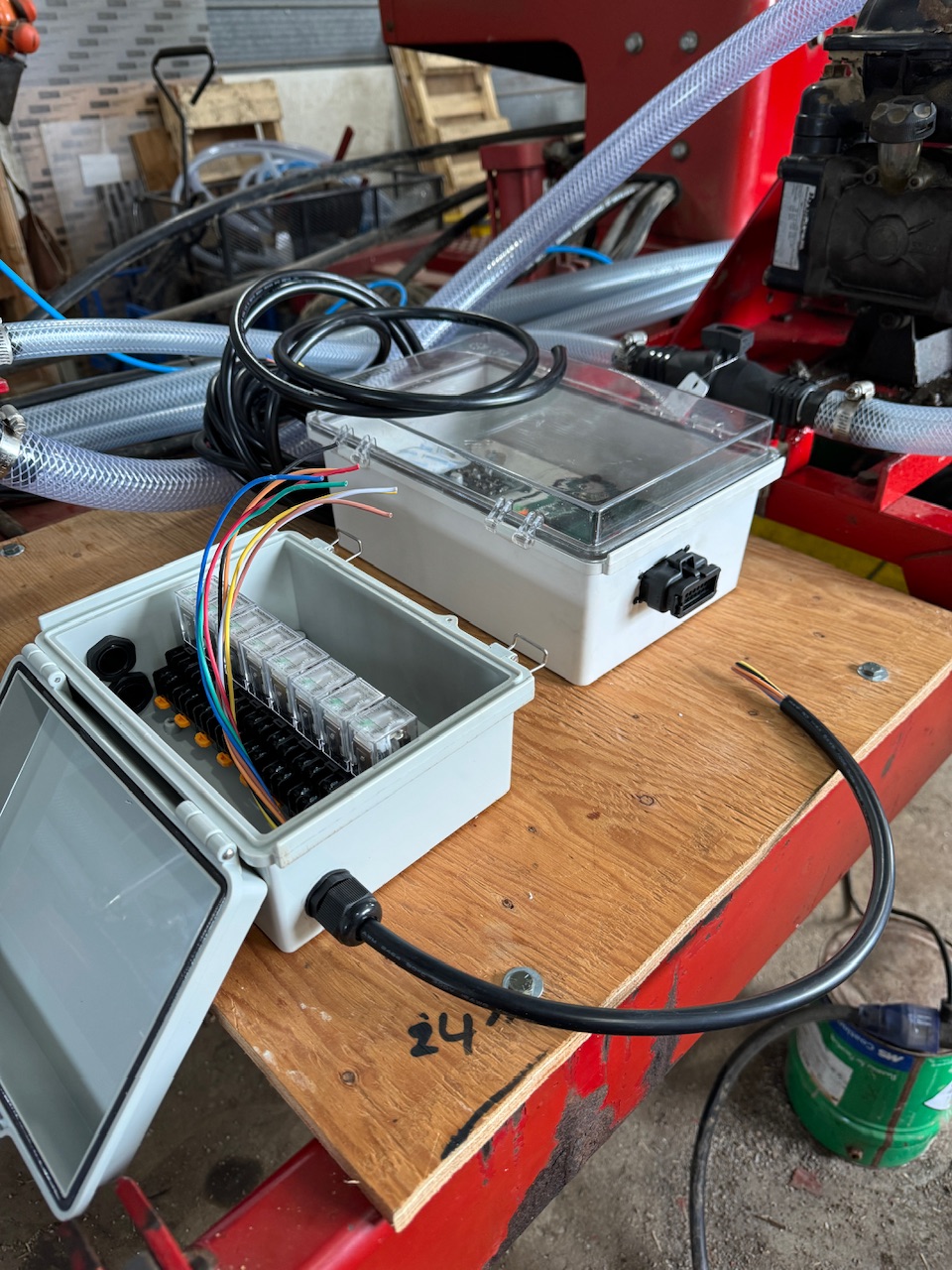
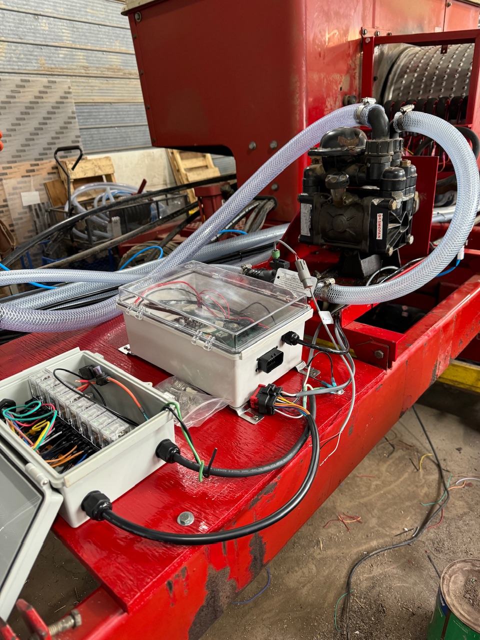
This is the connections to the planter tractor. There’s a 7.5 amp fuse in the power supply line, on the keyed power of the auxiliary power plug.
5 Likes
I’m thinking I should maybe add a work switch on the corn planter as well. Could I do that through RC11 somehow? I found this setting in the beta version I have right now, downloaded on January 24, 2025.
1 Like
That pcb version doesn’t have a work switch connection. It may be possible to use one of the flow pins if you are not using both. Or one of the pressure pins.
1 Like
Exactly what I was thinking of trying! I can just set the work switch pin to the appropriate pressure or flow pin that I connect to on the board then. I’ll see if I can get that working sometime.
1 Like