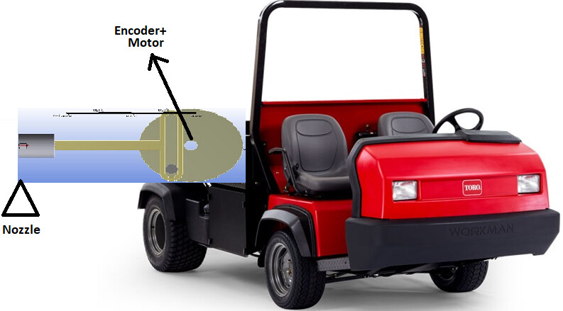
So, I’m working on a project with a friend to make a device for automatic painting of lines on the local highschool football field. They have one of those Toro utility trucks (like a gator type unit) that will hold the generator and airless paint sprayer. The idea is to use a solenoid valve right at the paint nozzle to turn the paint supply on and off. The truck doesn’t have power steering, so auto steering is kind of out. But the thought was to build a slide unit with linear guide rails, and then have a ballscrew and stepper motor or servo motor to move the nozzle left/right… I.e: Driver would drive the unit as straight as possible and guidance would keep the nozzle on the line so long as the driver didn’t run it out of travel…
I’m curious how well this would work, being that the reaction will be instantaneous, and that one couldn’t put a WAS on this as it would constantly be trying to bring the slide back to center… Any thoughts??
It can be a Scotch Yoke mechanism, with an encoder connected to the back of the motor, the position can be determined and forward-backward movements can be made. electric actuator and linear scale (sensor) may be another solution, but linear actuators are slow for this job (15-35mm per second.)
If you are going to do it with a ball screw, if the pitch of the shaft is larger, the movement will be faster, for example 10 mm or 20 mm in 1 revolution. And again, the position is determined by connecting an encoder to a DC motor.
I saw a news clip of a local high school that used a push one that operated the same way. You followed close to what was required and it corrected based on gps. It was screw style.
There’s a handheld cnc router that works along these lines. You look on the little screen and move the router close to where it needs to be and the steppers move the spinning bit to where it needs to be. Actually works very surprisingly well.
Not quite sure how you’d interface this linear mechanism with AgOpenGPS, though. Might need to create some dedicated software. I’d recommend a dual GPS setup for this. That way you can know exactly what your heading is so you can know what direction to move the nozzle.
Hasn’t AgOpenGPS been uses successfully with steering wheel motors? I would think one could do the same thing to run the linear actuator…
As for a dual receiver setup, is this something that is fairly straightforward in AOGPS? I’m not a programmer… I’m a Mechanic/Machinist/IT Guy that is really good with mechanical systems and computers, but programming/coding from scratch is not my strong point.
Maybe I just should plan on doing a steering wheel motor setup like alot of tractors have… There’s room on the football field to turn and get online before the boundary.
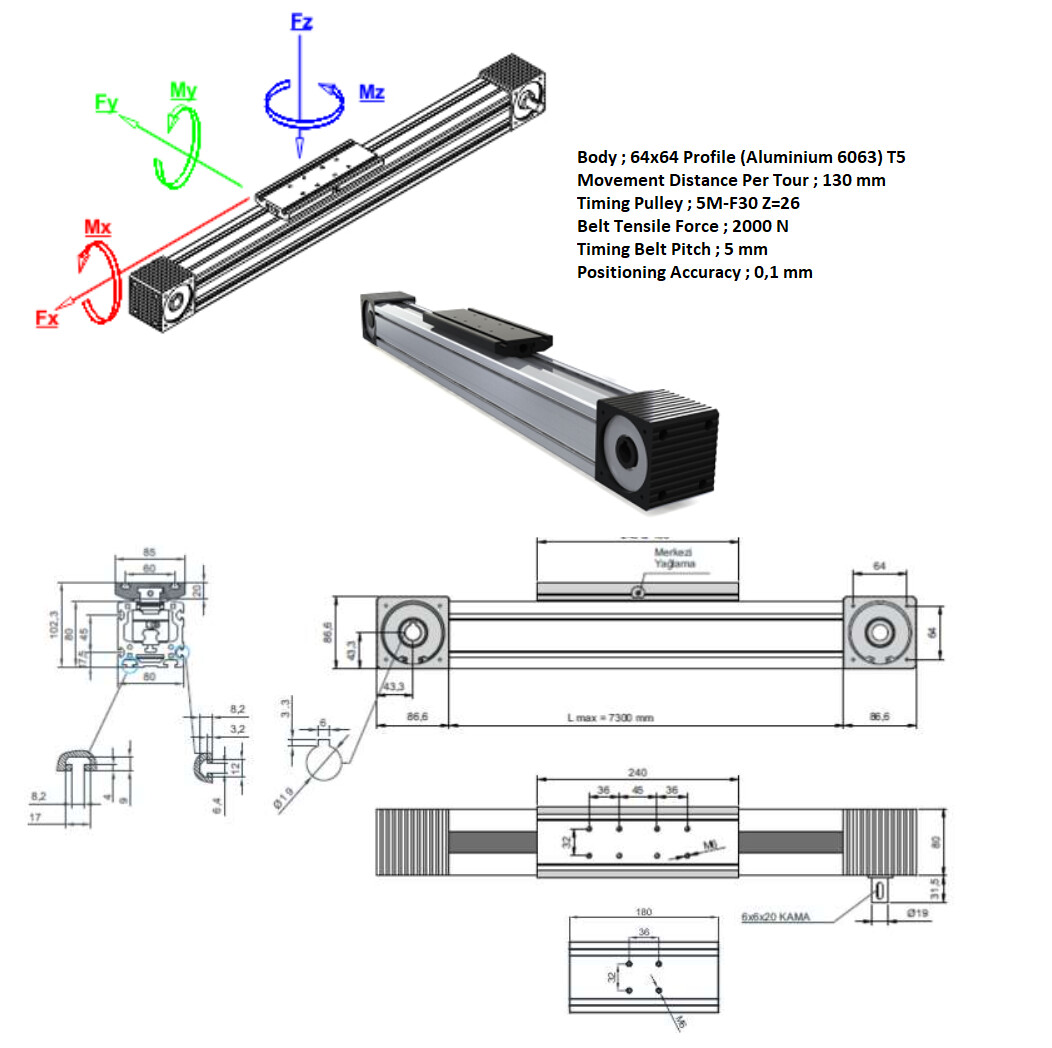
In fact, what if you connect a motor to the steering system of this vehicle instead of all this effort? There are many examples that turn the steering wheel with a DC motor from the outside, but of course, if there is no such option, the timing system may also make sense, because it can accelerate up to 300 mm in 1 second.
Sure. But that’s not what the OP needs to do. The AOG steering algorithms are based on heading, steering angle and ackerman geometry. What the OP wants to do is a bit different than that, and actually simpler. Basically you want to do simple error-based movements. For example if the machine is 0.5 metres left of the line (offset error), move the linear actuator 0.5m right. AOG can already calculate this offset, so you could take that value and translate it directly into actuator movement. I’m sure this can be done with existing AOG hardware (steering angle sensor could be used to determine actuator position, and the PID loop that moves the steering angle would move the actuator) but the software will require some tweaking. At least that’s one way to do it.
Another way is to mount the GPS unit itself to the nozzle that can move with the actuator, and then steer that (pure pursuit maybe) to the line.
Did you get anywhere with this. I am looking at doing a similar thing with the line marking. I was hoping to use auto steer but after playing with simulator mode I am currently trying to work out if the AgOpenGPS software is the best option.