The MD13S driver works with a 12 volt motor (24 volt motor). When I turn on 24 volts through the converter, the voltage at the driver output when the motor is loaded drops to 12 volts. Converter 10a. https://aliexpress.ru/item/1005001278356260.html?item_id=1005001278356260&sku_id=12000015558742375&spm=a2g39.orderlist.0.0.31b34aa6iGMujB
Try to do the same measurement with only 12 v in on md13s, and with same load.
I guess the result will be below 12 v due to resistance in the circuit and the fact that the motor is almost acting as a short with high loads.
when I connect 12 volts, without a converter, the input and output are 12 volts. In the program, the power is set to 255.
I connect the output of the 24 volt converter to the MD13S input. A 24 volt motor is connected to the output. When the motor is not turned on, the MD13S input is 24 volts. As soon as I press the button to the left or to the right, the wheels turn, but the voltage at the input drops to 12 volts. And so 12 volts remain until I turn off the power. After resetting, a voltage of 24 volts appears again. As soon as I press the power button, 12 volts appears. I connected the 2nd MD13S, the same thing.
I worked with this motor from 12 volts. But it is necessary to add power, not much does not keep up with the line. Everything in the program is already at its maximum. I connected the converter, but here it is a failure.
In first post you told 12 v at driver output.
With this new information I think you should test how many A the circuit is using at full left/ right (I guess you press buttons on the MD13s)
Maybe the dc dc converter has internal automatic restriction of Amps out?
Reset ? power off power on?
Maybe you have just passed dc dc converters maximum.
I suggest to work from inside AOG set max to eg. 100 (or less)= and try the Drive function in autosteer settings.
Then work your way up to the max maximum setting in AOG for the dc dc converter to stay “alive”
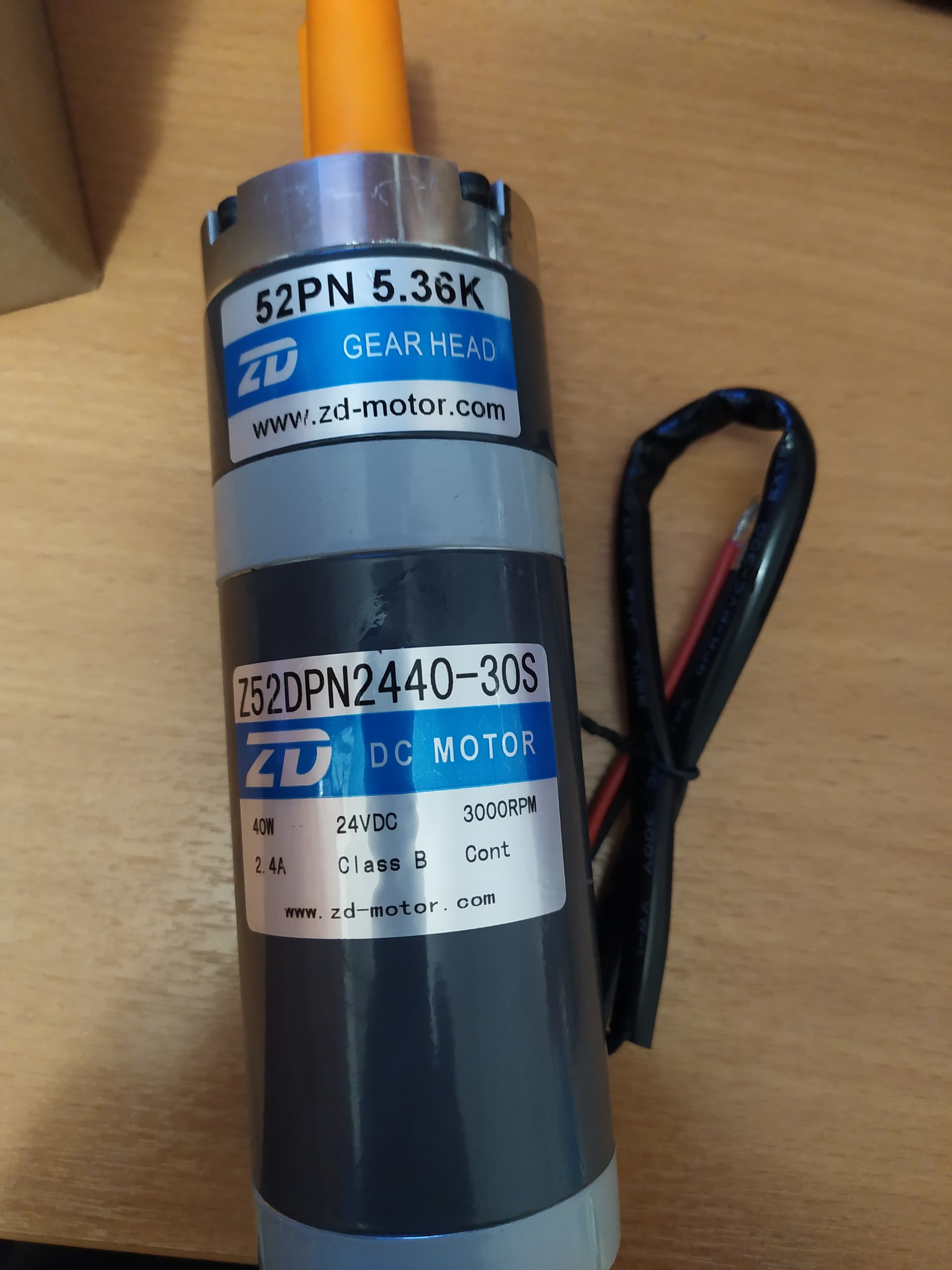
Edit: But something is absolutely wrong here, as the A on motor say 2.4 A!
Maybe startup current is high?
I also think that the starting current is large. I wrote out IBT-2. I’ll try again with him.Probably some kind of protection is working. I tried with no load, the motor itself at 360 ma start.
Cool you found a motor almost exactly like the fidgets.
What does your wiring between the 24v converter and the mds look like could we see a pic. The 24v ground on the converter is isolated, so it must only go to the mds input, if it touches another ground in the system for some reason it does not work.
I found this out trying to simplify wiring and it caused it not to work.
Thanks. The earth is not just isolated. This is probably the reason. I will connect differently.
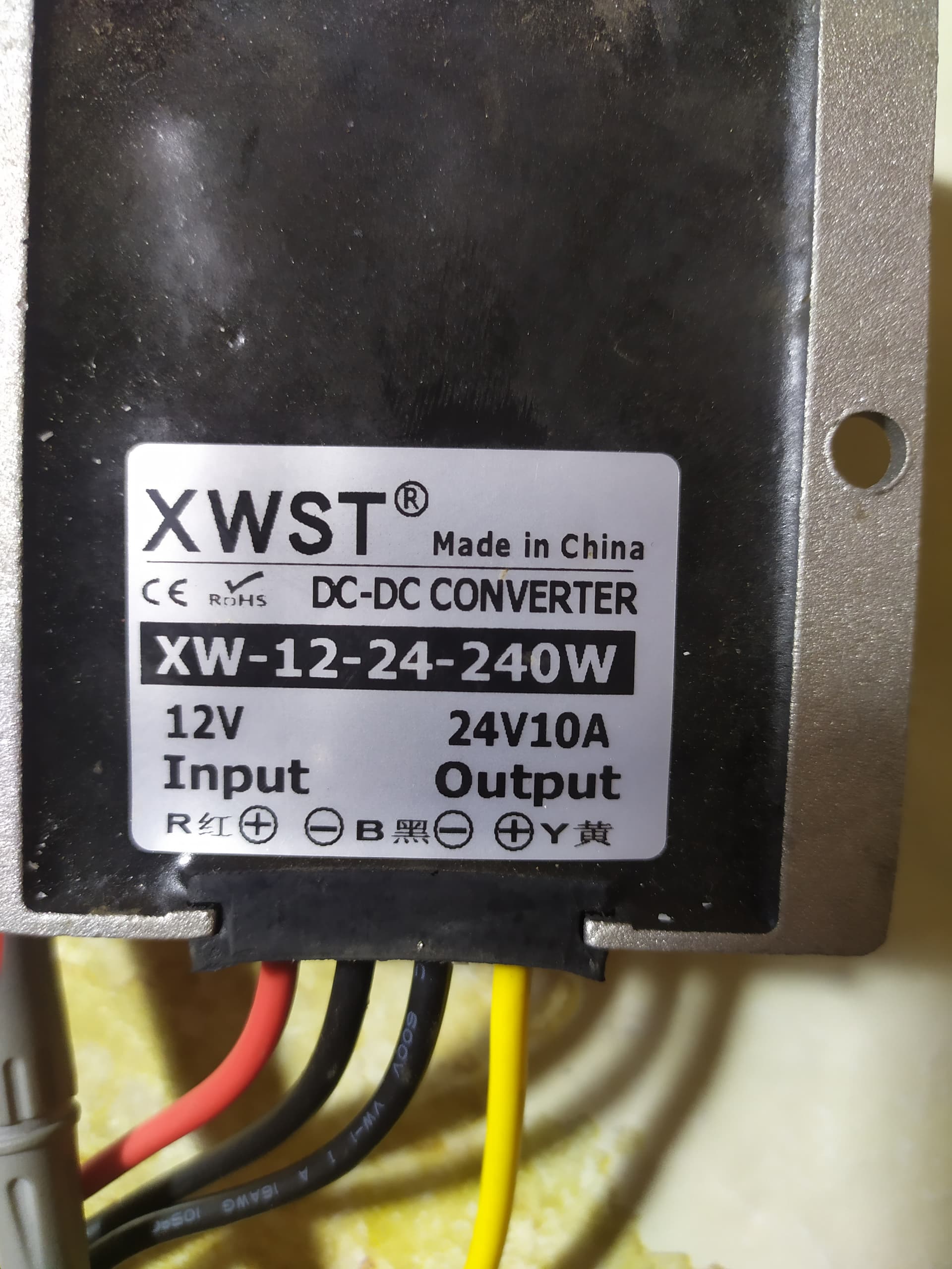
The inverter has a common ground for input and output. I measured the resistance. 2 black wires. The device showed 0.I do not isolate the earth in any way.
We are using same converter, when i had the negative next to the yellow to the aog board, and then board ground back to the mds it did not work.
Once the black and yellow went to mds directly no problems.
Another question, have you done the freewheel modification or is it a stock mds?
have you done the freewheel modification or is it a stock mds? I don’t understand this.
1 Like
There is a modification that allows the mds to sleep and disengage and allow the motor to turn freely. Otherwise the motor acts like an electric brake when auto steer is disengaged.
Its very handy, but will disable mds test buttons if not commanded to wake up.
Just seeing if the test buttons are still operable without intervention.
If the black and yellow are 24v tested by themselves, connected to the motor, the test button should turn it.
Also you could test direct converter to motor, with a 8a fuse just in case.
2 Likes
I haven’t done that yet. The buttons work. I swivel them left and right. Tomorrow I will try to connect the converter directly to the motor.
Today I tried to connect the converter directly to the motor to turn the wheels. The inverter has little power. When the wheel is turned, the voltage at the output of the converter drops by 12 volts. We need a more powerful converter.
1 Like
From the same Chinese brand I have used 15A and 12A converters without issue.
I think that that particular unit has just failed. At least now its certainly the converter.
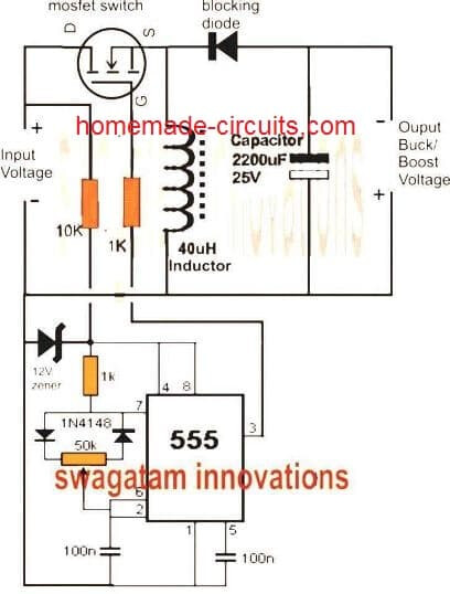
I think the reason for the goofy negatives is something like this boost diagram, it looks like the positive of one side becomes the negative of the other. This would explain why when I tied all the negatives together I had issues. Yellow and black directly to mds no issues.
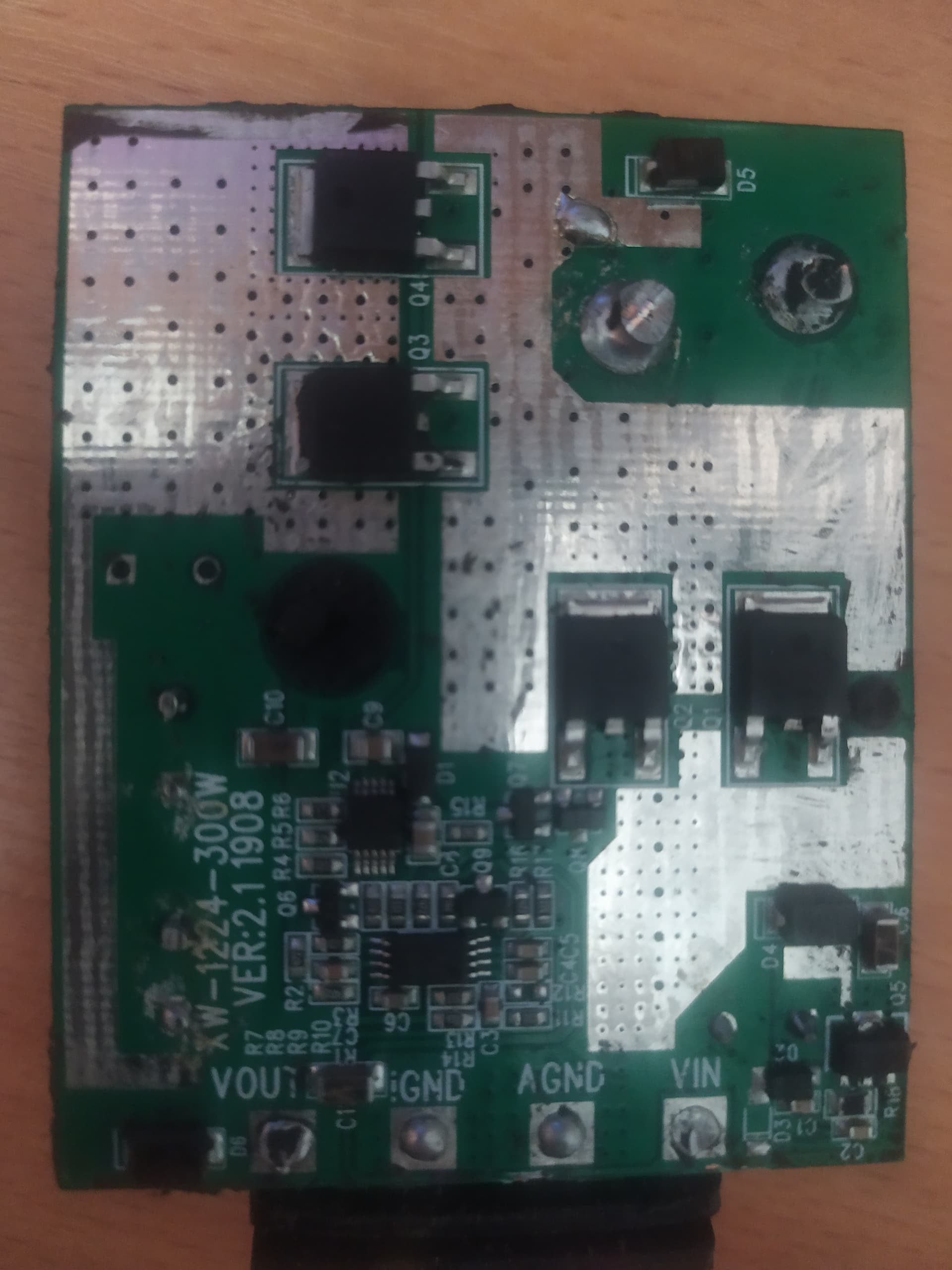
The grounds do look to be on the same trace, so I am unsure why when I wired it with both negatives to the AOG board and one wire back to the mds it did not work for me.
Thank you for taking the time to open it up!