Yes, you have that correct.
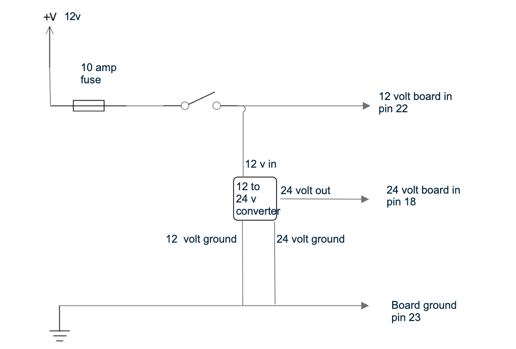
I’m at about the same point as you with the same setup. I havent actually wired it up yet but here is how i plan to do it. pins 5 and 6 to motor.
1 Like
Yes - that is as I have now done except not using 24v gnd (as above on this strand) as I assume it picks up gnd from the board. Having tested in the tractor I am also installing a quick release switch inline between amp pin 5 and motor so if I need to override quickly I can.
it looks like you are right. the 24 volt ground is not needed. There is continuity between the 12v and 24v ground in the converter
Hi,
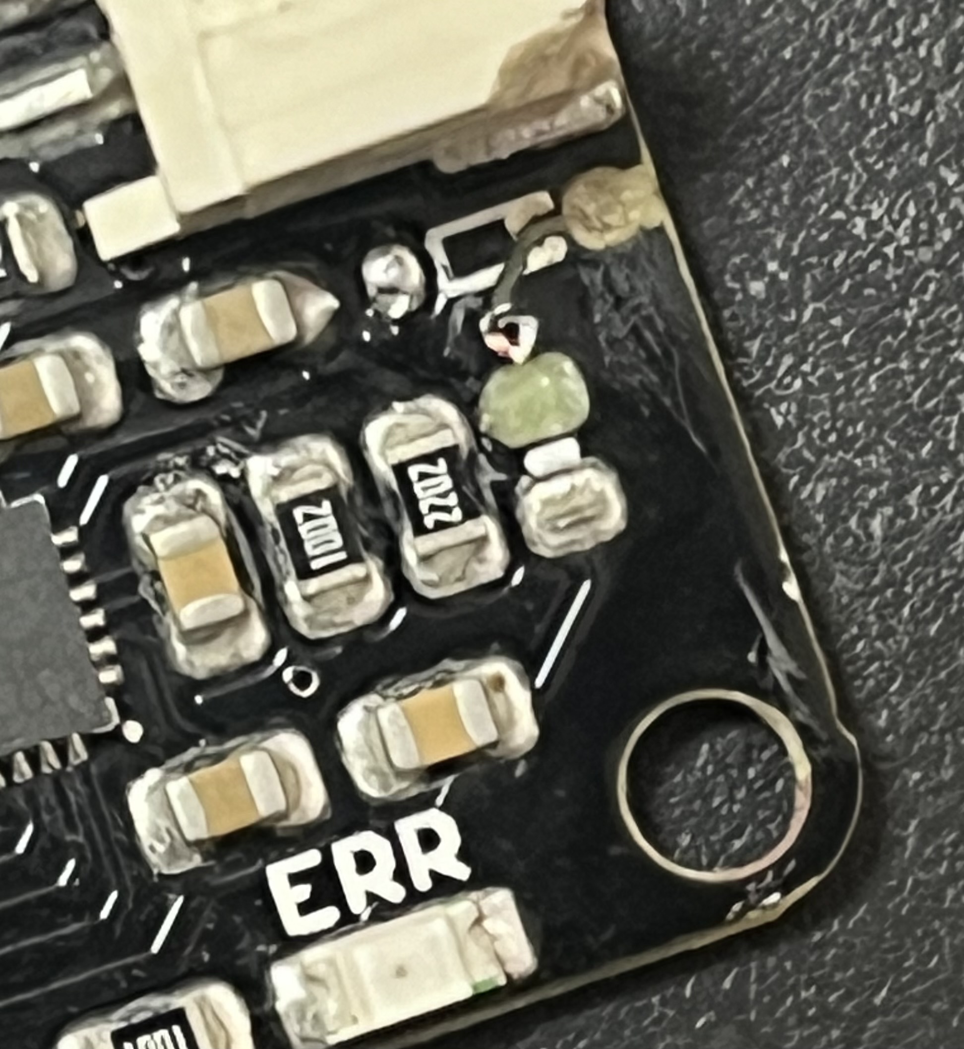
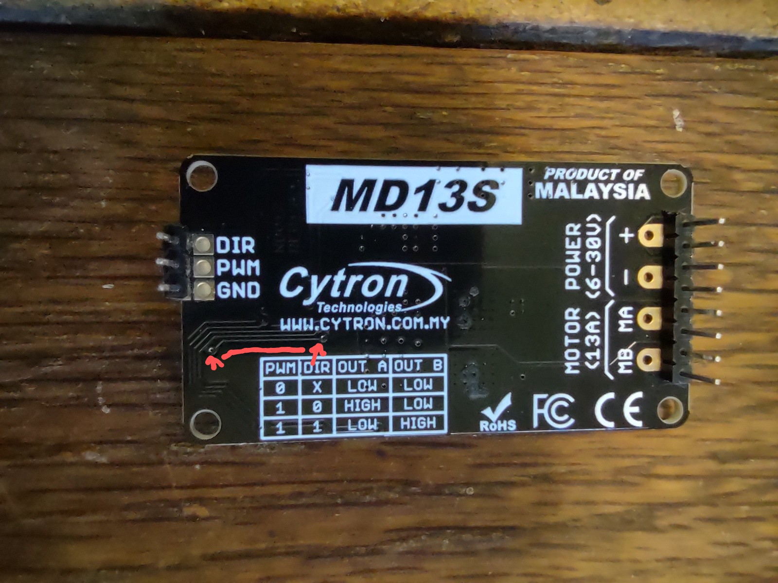
While im trying free wheel mod , i broke my md13s. The two points mentioned for soldering are also out of use. Is there any way to get this card working? or Do I need to get a new card?
Who did the 3D printing for you if you don’t mind me asking?
I would advise just get another one or two since they aren’t to expensive. I don’t understand if it is broken other than the pads and the trace being ripped off. This is the same trace on the back which you could potentially try to solder to but it would be considerably more difficult thing that the original mod.
That was me ![]() Send me a message or I can try to get in touch with you later. I’ve got a set printing right now that I should have ready in a few days.
Send me a message or I can try to get in touch with you later. I’ve got a set printing right now that I should have ready in a few days.