Hi! I am bench testing my setup (micro 4.1 aio) using agio5.7, single connected NC and contact point of removed resistor to have the free wheel mode on the cytron md13s, connected was to ampseal 1, 2 and 4, phidget connected to ampseal 5 and 6, positive from output of 24v upconverter to ampseal 18 (negative not connected), and input of upconverter positive and negative as well as to ampseal 22 and 23 to 12v.
Results: gps works, bno works, and was works. There’s no indication if the motor is working. No whishing sound. Manual testing does not work anymore because of the free wheel modification.
Question: Is there a way to test if the motor works while bench testing?
If you create a field and then create an AB line in the simulator mode, you should get some movement out of the motor when you engage the auto steer onto the AB line and then should be able to change the speed/direction of the motor by moving the WAS.
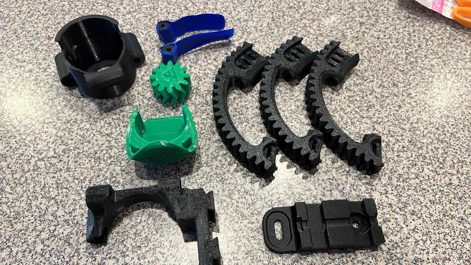
Hi! Ok will do that. By the way I got the printed parts and they look very nice. Thx.
1 Like
Open the steer panel, expand it, engage DRIVE mode (the little tractor) and use the arrows to set direction. Wheel should turn.
2 Likes
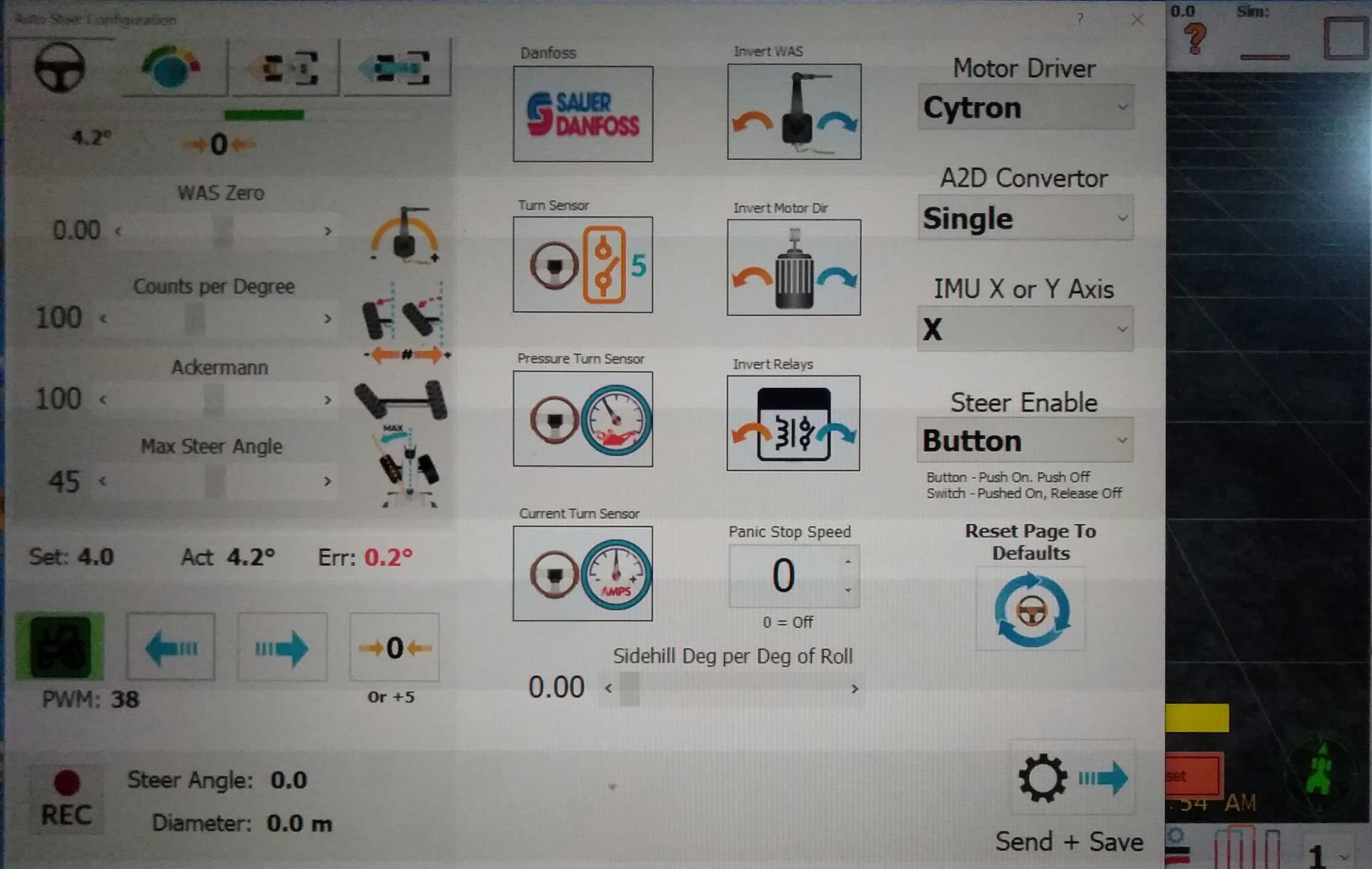
Hi GPierce, Andyinv and all! I made a field, then AB line, expanded steer panel and thru the switch turn the little tractor to green. Then I press on the either the left or right arrow which resulted in the pwm increasing and decreasing accordingly. Even with these encouraging signs that there’s communication between the board and the software, the motor stayed still! Any suggestions on how I make the motor move! Thx
Post a photo of your board. Are there lights on the cytron? What happens when you press MA/MB on it? You did add the selectable power input (12v or 24v) to the cytron, yes?
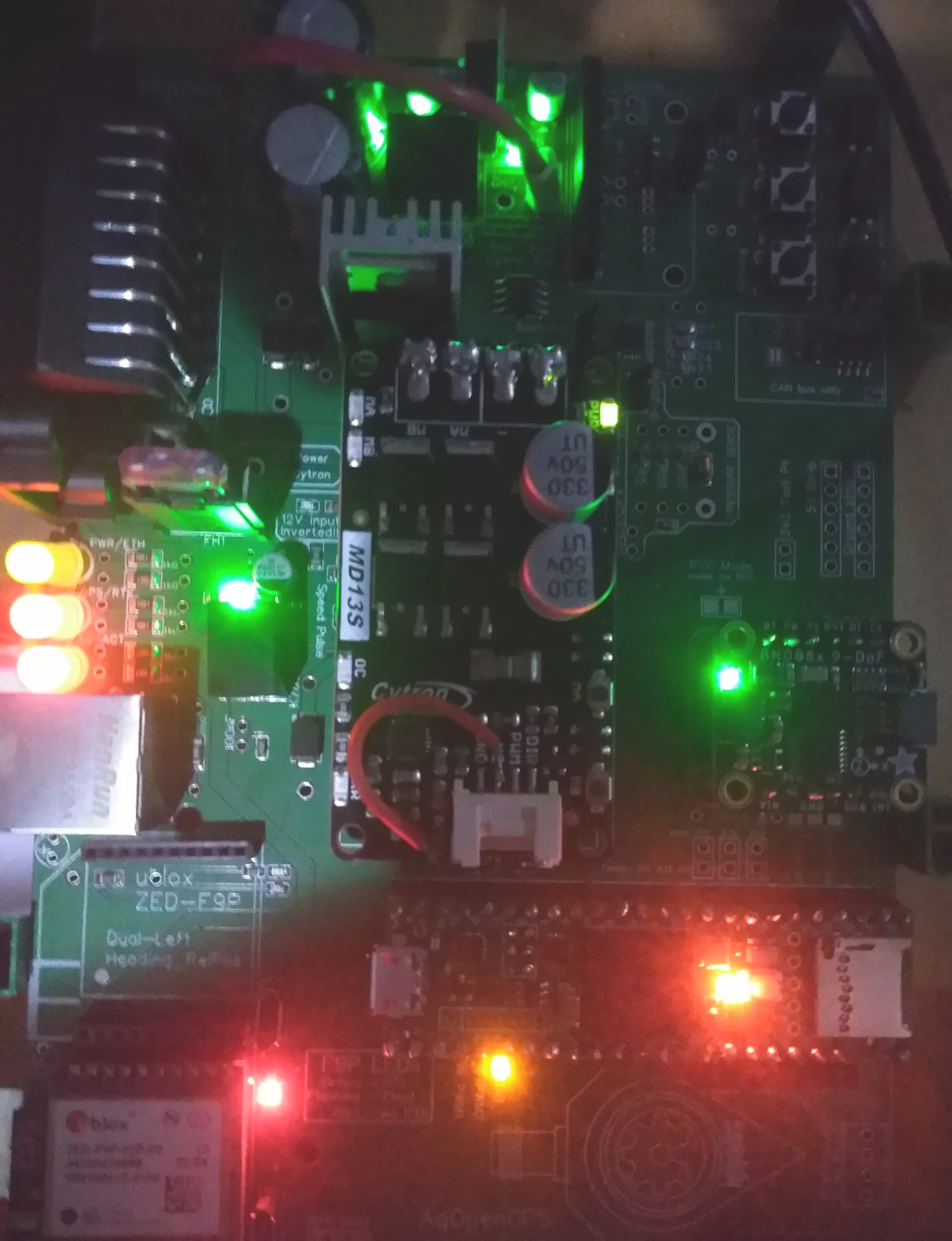
Here’s the image of the board (apologies for the quality). The cytron green light is up and no other. MA/MB used to work before I did the freewheel modification. Yes, I selected the 24v and a quick check on the multimeter confirms the voltage that goes into pin 18 does have the required voltage.
Maybe a closer look at your cytron mod? Did you remove both the diode and resistor? I don’t know if this is even a logical solution, just trying to think why the cytron wouldn’t be working correctly. AndyInv is the expert here!
After the free wheel mod, MA/MB buttons don’t work without using PWM2 “enable” signal which generally is connected via the 4 pin connector.
1 Like
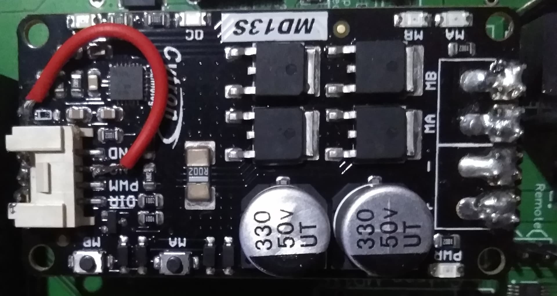
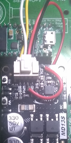
This is the close up of the cytron. Diode and resistor removed. Indeed the MA/MB doesn’t work anymore which makes diagnosing the problem or at least eliminating obvious source of the problem difficult.
I believe you can apply 3.3 v to the red wire, and ma plus mb should work again
Alright so I’ll apply positive 3.3v from one of the output pin of the aog board at either end of the freewheel mod red wire (either at NC or base of removed resistor[diode]) and it will make the MA/MB work? Will the restored test capability only work as long as 3.3v is applied (I guess that’s obvious)? Will the md13s be mounted on the board while connecting 3.3v of I have to remove it from the board? Thx
Just an idea and similar happened to me but i didn’t do the free wheel mod. Pressing the buttons on the cytron would power up the motor but i couldn’t get the ‘drive’ button to work the motor same as you. After alot of testing and head scratching it turned out that the teensy i bought with the header pins already attached had a small blob of solder between 2 pins, i removed this and all came to life. Might not be your problem but worth a look
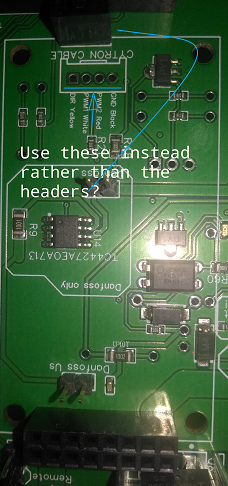
It looks like you are using the 3 pins on the board to drive the cytron. My experience is with the mod you need 4 wires from the through hole below the cytron.
The board buttons still will not work but the “Drive” button will!
1 Like
You mean the one illustrated in the image?
1 Like
Exactly! With the freewheel mod, you need PWM2 in that 4 pin connector to enable the Cytron.
1 Like
Great! May I ask how to go about mating the 3 point slots on the cytron to the 4 slots on the board? Thx.
You use the 4 pin connector/harness that was included with the cytron. I usually cut it in half, solder to the pcb and plug into the cytron. That’s why you have the red wire on the cytron freewheel mod.
1 Like
SUCCESS!!! I am happy to report that the cytron with the freewheel mod finally moved the motor in the direction opposite the was. My soldering skill is terrible so since the three pin header has connectivity to the yellow, white and black wire through hole, I only solder the red wire between the cytron and the board. Thank you very much to m_elias! Thx also goes to gpierce for the tach motor and universal segmented wheel printing of potatofarmer design and the rest of you guys. 'Will finally be able to move to the next stage of this project!!!
6 Likes
This is probably a stupid question but I am at the point of testing my system using v4_1, Cytron, phidgets 24v motor and 24v up converter. My WAS set up seems to be working fine but I am not getting any motor movement at all and I imagine it is due to my wiring !
From the above do I understand that my main tractor 12v in and ground go to both the ampseal 22 & 23 and also the 12v in goes to the input of my 24v upconverter ? As I read above my 24v from the upconverter goes to the ampseal 18 and then the ampseal 5 & 6 go to the phidgets motor ?
This is not quite as I have it but if someone can confirm then I will set it up as that.
thank you