I was able to get Matthias’s section switches to communicate over WiFi on ESP32. I was wanting to use “zone” on switch inputs. The inputs came in as sections. It also seems the inputs need external pull-up resistors. They weren’t stable. Could someone help me with this please? TYIA
may you put a circuit diagram of what you have build? I didn’t understand the question.
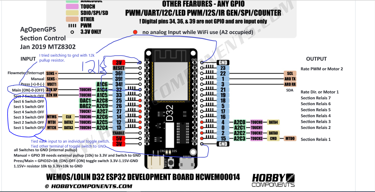
The Main and the rate switch is a (on)/0/(on) toggle switch witch 0V/1,375V/3,3V to the ESP. The Auto/Man and the section switches are on/off switches to GND or 3,3V with internal or external pullup or pulldown. Software would support both
Can supply diagram later. Currently only have toggle switches for main and sections 1-6 tied to inputs on PDF. Other terminal of switch all tied together with one wire to gnd of esp32. Software was copied from all separate files on Brian’s pcb and firmware GitHub under MTZ. I only altered WiFi sign in info. I don’t remember if there was any other setup code on ino I altered. Definitely a lot of different files or tabs to make it compile. I would like to have 1 esp for 6 zones in tractor. Another esp on planter for 12 sections to control. Prefer Ethernet cable for comms. I’m sure WiFi will work fine. I just would rather have rj45 connectors and cables if not much with involved to do that.
Thanks
I just noticed you said the different voltages for auto an main. I didn’t do that. I just left input open, or connected to gnd with switches. I suppose you use resistors for voltage dividers?
ESP_32_Section_Conrol.zip (30.0 KB)
I didn’t get a chance to draw circuit diagram. I made notes on the diagram I used.
The stability with inputs was my fault. I must need glasses. Thought I tied to GND it was CND instead.
Hi
I have an issue with uploading firmware, i can only verify at the moment. because i am in process of getting an ESP32 instead of nano.
Start of error code:
"
C:\Users\jonsa\Desktop\test\AOG_SectionControl_ESP32\zAOG_ESP32Ping.cpp: In member function ‘bool PingClass::ping(const char*, byte)’:
C:\Users\jonsa\Desktop\test\AOG_SectionControl_ESP32\zAOG_ESP32Ping.cpp:61:9: error: ‘WiFi’ was not declared in this scope
61 | if (WiFi.hostByName(host, remote_addr))
| ^~~~
C:\Users\jonsa\Desktop\test\AOG_SectionControl_ESP32\zAOG_SC_Network.ino: In function ‘void WiFi_STA_connect_network()’:
C:\Users\jonsa\Desktop\test\AOG_SectionControl_ESP32\zAOG_SC_Network.ino:347:54: error: conversion from ‘unsigned int’ to ‘IPAddress’ is ambiguous
347 | if (WiFi_STA_connect_call_nr == 0) { WiFi.config(0U, 0U, 0U); Serial.println(“enable DHCP for WiFi”); WiFi_STA_connect_call_nr++; }
| ^~
In file included from C:\Users\jonsa\AppData\Local\Arduino15\packages\esp32\hardware\esp32\3.0.5\cores\esp32/Arduino.h:196,
from C:\Users\jonsa\AppData\Local\Temp\arduino\sketches\F1EC8C0CA2635295B3A66D6BDE8A64AA\sketch\AOG_SectionControl_ESP32.ino.cpp:1:
C:\Users\jonsa\AppData\Local\Arduino15\packages\esp32\hardware\esp32\3.0.5\cores\esp32/IPAddress.h:115:3: note: candidate: ‘IPAddress::IPAddress(const ip_addr_t*)’
115 | IPAddress(const ip_addr_t addr);
| ^~~~~~~~~
C:\Users\jonsa\AppData\Local\Arduino15\packages\esp32\hardware\esp32\3.0.5\cores\esp32/IPAddress.h:72:3: note: candidate: 'IPAddress::IPAddress(const char)’
72 | IPAddress(const char address);
| ^~~~~~~~~
C:\Users\jonsa\AppData\Local\Arduino15\packages\esp32\hardware\esp32\3.0.5\cores\esp32/IPAddress.h:69:3: note: candidate: 'IPAddress::IPAddress(const uint8_t)’
69 | IPAddress(const uint8_t *address);
| ^~~~~~~~~
C:\Users\jonsa\AppData\Local\Arduino15\packages\esp32\hardware\esp32\3.0.5\cores\esp32/IPAddress.h:67:3: note: candidate: ‘IPAddress::IPAddress(uint32_t)’
67 | IPAddress(uint32_t address);
| ^~~~~~~~~
In file included from C:\Users\jonsa\AppData\Local\Arduino15\packages\esp32\hardware\esp32\3.0.5\libraries\WiFi\src/WiFi.h:33,
from C:\Users\jonsa\Desktop\test\AOG_SectionControl_ESP32\AOG_SectionControl_ESP32.ino:192:
C:\Users\jonsa\AppData\Local\Arduino15\packages\esp32\hardware\esp32\3.0.5\libraries\WiFi\src/WiFiSTA.h:133:25: note: initializing argument 1 of ‘bool WiFiSTAClass::config(IPAddress, IPAddress, IPAddress, IPAddress, IPAddress)’
133 | bool config(IPAddress local_ip, IPAddress gateway, IPAddress subnet, IPAddress dns1 = (uint32_t)0x00000000, IPAddress dns2 = (uint32_t)0x00000000);
| ^
C:\Users\jonsa\Desktop\test\AOG_SectionControl_ESP32\zAOG_SC_Network.ino: In function ‘void WiFi_Start_AP()’:
C:\Users\jonsa\Desktop\test\AOG_SectionControl_ESP32\zAOG_SC_Network.ino:358:13: error: ‘SYSTEM_EVENT_AP_START’ was not declared in this scope; did you mean ‘WIFI_EVENT_AP_START’?
358 | while (!SYSTEM_EVENT_AP_START) // wait until AP has started
| ^
| WIFI_EVENT_AP_START
exit status 1
Compilation error: ‘WiFi’ was not declared in this scope
"
End of error code.
Hope anybody can shine som light on this issue.
So you don’t have the esp yet? Guessing it has wrong chip or board entered in IDE. Trying to compile with a nano selected would give you errors. Is correct board selected? We have had great luck with Matthias’s esp. We only use it for external switch input.
Hello. I took the .zip file from the post above. (No zAOG_ESP32P.ccp included)
Using Arduino IDE 2.3.3 to compile mit board “ESP32 Dev Module” selected:
Modify as detailed below to compile (some warnings will still remain)
Modify Line 302 in zAOG_SC_Network.ino from
if (WiFi_STA_connect_call_nr == 0) { WiFi.config(0U, 0U, 0U); Serial.println(“enable DHCP for WiFi”); WiFi_STA_connect_call_nr++; }
to
if (WiFi_STA_connect_call_nr == 0) { WiFi.config(INADDR_NONE, INADDR_NONE, INADDR_NONE); Serial.println(“enable DHCP for WiFi”); WiFi_STA_connect_call_nr++; }
Modify Line 313 in zAOG_SC_Network.ino from
while (!SYSTEM_EVENT_AP_START) // wait until AP has started
to
while (!WIFI_EVENT_AP_START) // wait until AP has started
Add new Line 46 in zAOG_SC_EEPROM.ino between } and }
return 0;
So you had same error? Sorry that zip file was before I had switches, and relays operational now that I think about it. I also ended up connecting straight to esp wifi and not using router. Worked great last spring on planting. I am using nano with Ethernet adapter for relays. Only esp and wifi for switching sections and whole planter from man -off -auto.
Thank you hagre for reply.
I ended up finding a project made by Xilofeon (migth be mispelled). This was more basic in the code and works with a nano I have at the moment.
I used ChatGPT to alter code to work on 5v as on signal instead of ground.
I have not implemented yet, but plan is to integrate with physical switches for a Danfoil Concorde.
I hope to use normally closed switches so I can use sprayer without section control. So it will be signal from AOG = off.