I saw your setup with the WAS on the T5 New Holland. it looks really good!
what kind of WAS did you use here?
Are the 3D casing files on this forum? Would love to get this on my tractor aswell.
update: ordered the PCB’s, the Teensy, the BNO and the GPS stuff. So next stop is the hardware on the tractor. hopefully there will be a good RTK signal nearby.
The cover is a bit over engineered as I was learning Onshape and 3d printing at the time. It fits on the hub with magnets and the sensor is upside down rotating around the hub axis with fixed part attaching to the grub screw a little ways onto the axle. Printed in PETG and hasn’t been busted off yet. It covers a grease nipple so I need to either simplify removing the assembly or get an angled grease nipple.
It’s not a particularly effecient use of the sensor travel compared to a linkage based setup (relatively small travel angle) and Ackerman is significant. U-turns at higher speeds turns one way better than the other which probably means I need to fiddle the Ackerman a bit more.
haha it looks really nice, can tell you put a lot of thought into it!
I’m not sure yet what kind of setup i want to do for my WAS, but just thought yours looked really nice.
did give me some food for thought tho, never really thought about the Akkerman effect on the WAS before.
the placement right on the steering knuckle will increase the Akkerman effect right? Am i right when I say that this effect should be less when you place the WAS with a link onto the steering cilinder?
Other question: what would be the main reason to go for a 24V motor, is it just to have some extra power? seems to me that a 12V should be able to do the job and it saves you a converter.
update: teensy is in (man that’s tiny) looking up all other hardware parts now for the autosteer.
When you adjust Ackermann correctly, then steering around the middle (straight ahead) is not affected. You should also be able to set Ackermann so U-turn work same to both sides.
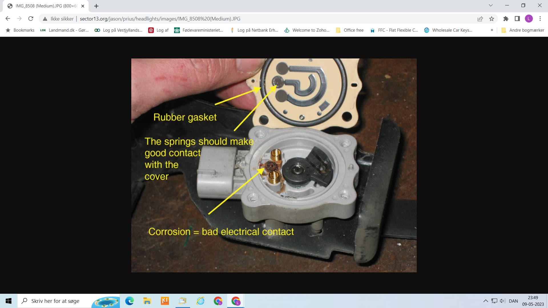
The Prius WAS is a potentiometer not a Hall effect sensor, like many other WAS used with AOG. But I admit the low price is tempting.
This is the inside of a Prius WAS that got water inside.
Yeah they can be considered a consumable. I mounted it upside down to avoid dust getting in through the seal. I keep a spare and the one I had fail had a dicky seal, so maybe the cheap ones have failed QC.
Ackerman is adjusted in the software and adds a factor to the steering in one direction and that works just fine, however it’s not quite that simple in real life as it isn’t linear. Your tractor has a tierod across the front so it would be fairly straightforward to mount the WAS to the axle closer to the pivot point and have linkage connected to the centre of the tierod eliminating Ackerman altogether. You ca also use linkage to "amplify " movement to use the full range of the sensor.
That’s how I did my last tractor and it was literally tied to the axle with fencing wire. The new setup, while much prettier, is arguably less functional. It also tends to pickup a bit more mud in wet conditions.
to be honest, just to get started I did order the lexus/toyota sensor off of Ali.
might not be super durable but it will get me started to set my systems up. I’ve seen a few very nice Elobau sensors but they are quite expensive, maybe I’ll go to a car breaker or something in the area to look for a OEM sensor for cheap.
I actually bought som cheap ordinary potentiometers for my bench trails. I also have a 12v motor for the trails. Got informed that the v4 bord has arrived at our local post office. Things are getting forward👌
Hello,
Hope the journey building your system is going well! There are a bunch of ways to build a base station with the F9P. And before I go any further I hope I’m not stepping on anybody’s toes…so I built the most basic base station set up I could find with the help of this awesome community!! Just consists of a F9P and an xbee radio on top of it. Works pretty good and its portable! If you are interested I would be more than happy to share pictures and information on it. Its simple and not the prettiest. Function over form hahaha. Cheers! And good luck
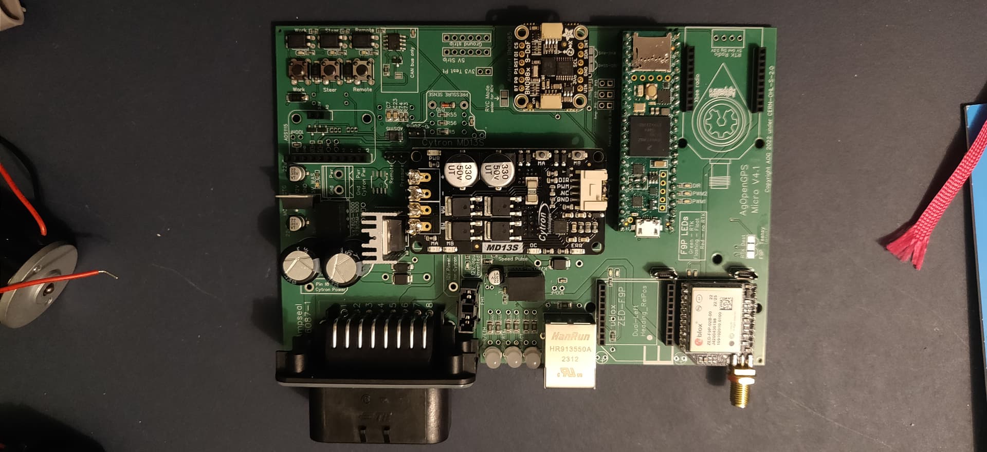
Hey guys! Just a small update from my side. So i’ve been waiting for all kinds of parts to come in and i have got most of it now. Jlcpbc didn’t have one of the sensors so i ordered the pcb without them but now im waiting for the AliExpress parts to come in. Ive soldered my first headers lol which was a steep learning curve but i got there! Next steps will be linking the teensy and f9p to the computer to get some files on them (if im correct) then solder the missing current sensor smd (which will be another learning curve) and then get some power to the board. Im going to use a 24v motor , which is absolutely tiny lol but the ali specs said it was up for the job so hope those specs are correct . So going to solder the pwr wire for the md13s. Does anyone know what to go with that ground terminal next to the pwr terminal? You need to solder that too? Next i’ll need some 3D printed parts to fit it all to the tractor later. Here are some pics. Any advise is always welcome. Jd4955 sure i’d like to see your project aswell, i dont know yet if there is free rtk available here, Will see.
Things are progressing slow but steady, i’ve soldered the smd current sensor, which was a real pain tbh. eventually i invested in some better flux and a thicker flat solderingiron tip which kinda did the job, it’s not pretty but the connections are made.I’ve made a rudimentary wiringloom to test with.
i’ve set the software on the teensy, which was really easy.
Next step setting up the GPS
edited: because of thread rules, moved question to hardware thread.